大量生産向け板金製造 サービス

10年以上の板金加工の実務経験を持つSR MFGは、長期的で再現性のある供給を必要とする部品やアセンブリを、量産に対応したスケーラブルな生産体制で支援します。.
生産見積もりを依頼
NDA対応可能
DFMレビュー込み
STEP / DXF / PDF対応
24~48時間で見積もり
1,000個以上

中量から
大量ロット向けに最適化

専用治具

専用治具による
単価低減

安定した再現性

全バッチで
一貫した品質

バッチトレーサビリティ

完全なロットトレーサビリティと
ドキュメント管理

大量生産向け板金製造とは 何か?

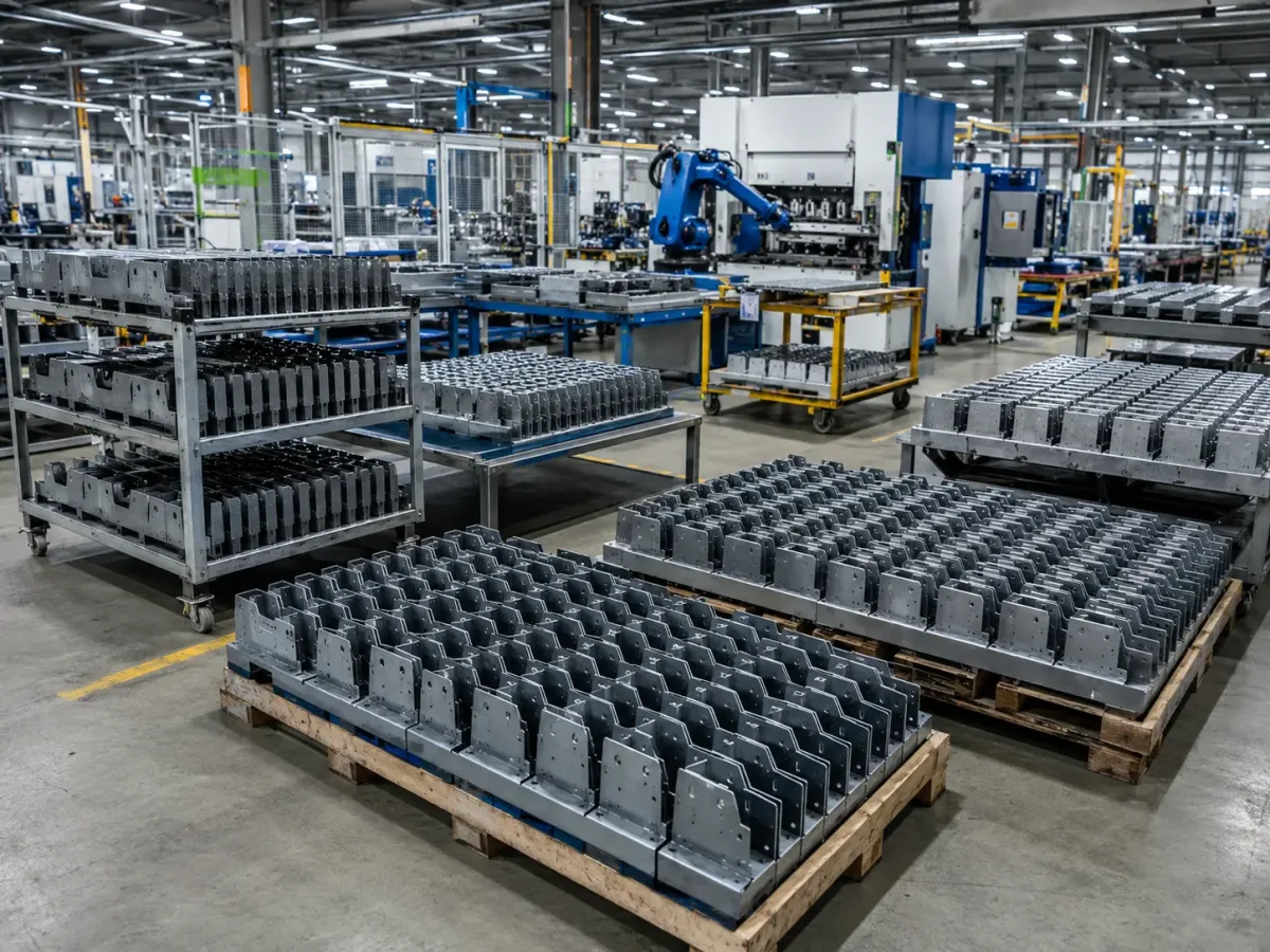
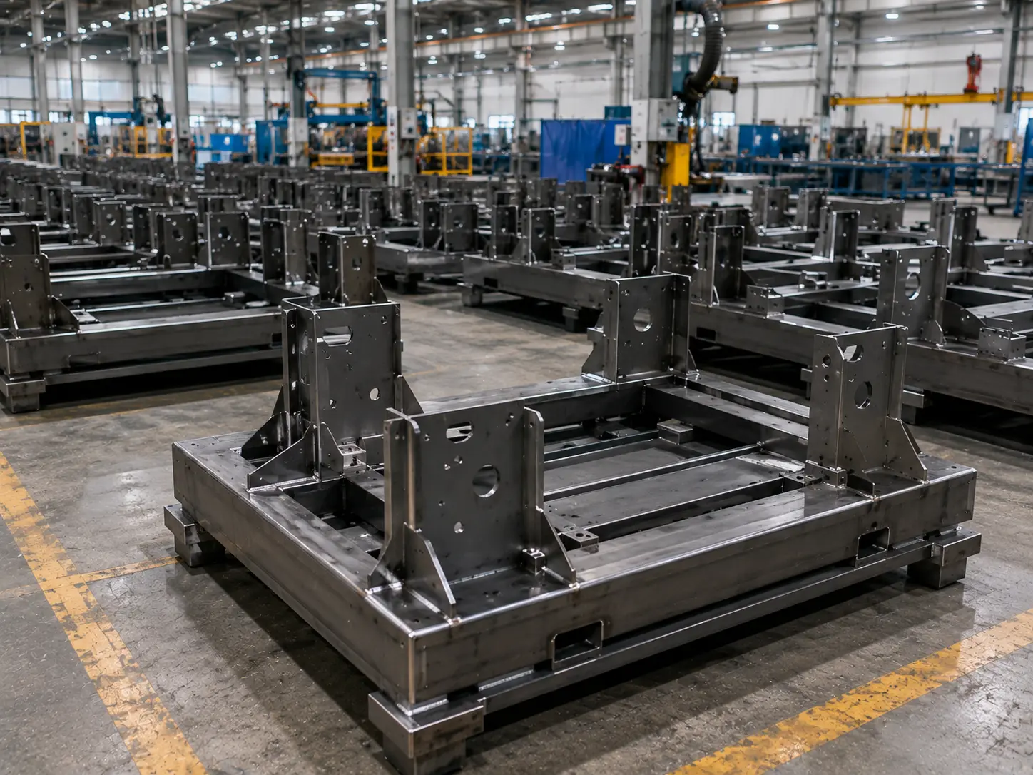
High-volume sheet metal manufacturing with standardized batch production and repeatable output

大量生産向け板金製造とは、一般的に 連続的で標準化された大規模生産 を指し、薄肉金属を対象とします。多くの場合、 約6 mmが板金と厚板を分ける実用的な境界として用いられます, (用途によります)。.

図面のリビジョンが安定し、変更が適切に管理されるようになると、生産は通常、 ライン型・自動化駆動のアプローチへと移行します。専用治具、タクトタイム工程、そして合理的な場合は金型ベースのプロセスを使用します。大量生産プログラムの核心的な目標は、 スループットの向上, 単価の低減 (初期投資をより多くの部品に分散させることによる)、そして バッチ間でのより一貫した結果.

どのようなプロジェクトが 大量生産向け板金製造?

大量生産を必要とするか 重要なのは単に「部品数が多い」ことではなく、プログラムを. 再現可能なサイクルと一貫したアウトプット に導くことです。需要とリビジョンが安定していれば、自動化、専用治具/ツーリング、標準化された工程を用いて、同一または極めて類似した部品・アセンブリを継続的に大量生産でき、生産ペースを需要に合わせることができます(多くの場合、).
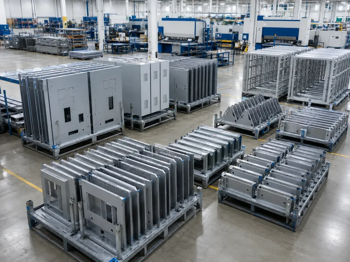
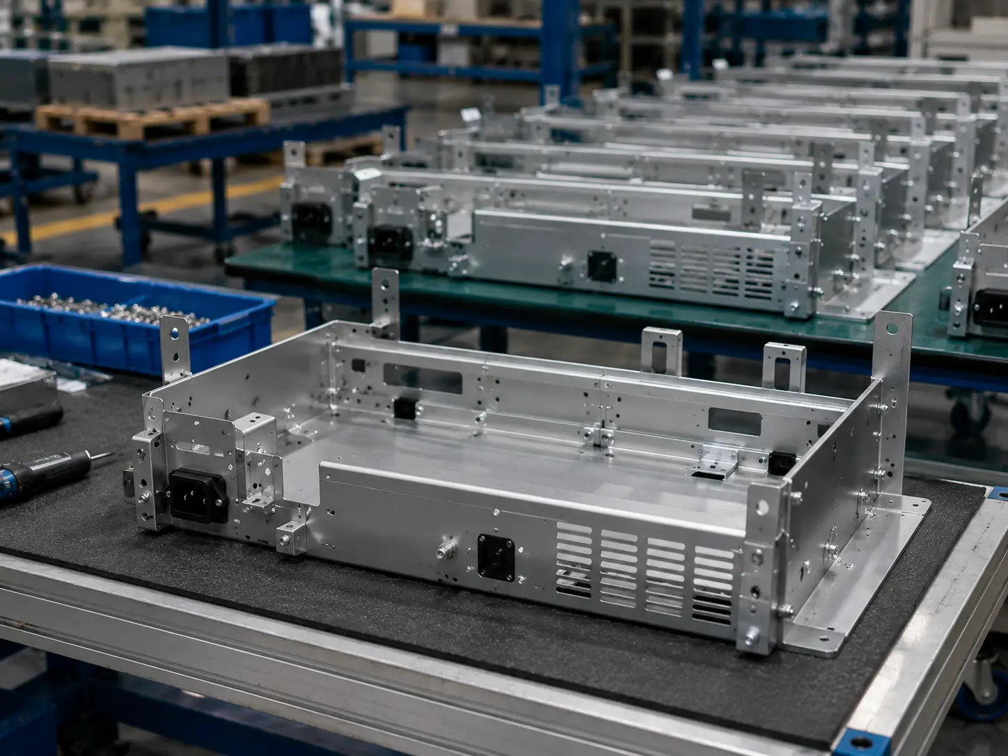
High-volume sheet metal projects including enclosures, panels, guards, frames, and OEM assemblies

タクトタイム

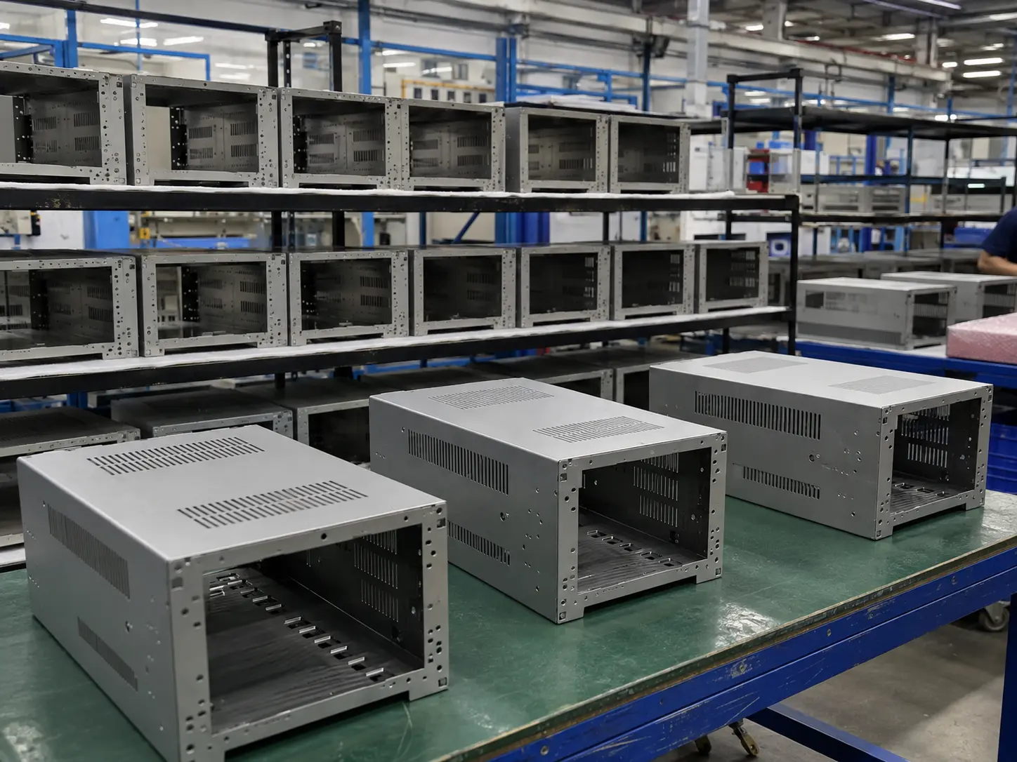
High-volume electronics enclosures and metal housings

で管理されます)。

大量生産に最適なプロジェクト

High-volume automation equipment panels and mounting plates

電子機器筐体

ラック、ハウジング、制御ボックス、パネル

High-volume machine covers guards and access panels

自動化設備パネル

制御盤、サイドパネル、取付プレート、ブラケット

High-volume welded structural frames and machine bases

機械カバー・ガード

溶接フレーム、ベースプレート、支持構造物、機械ベース

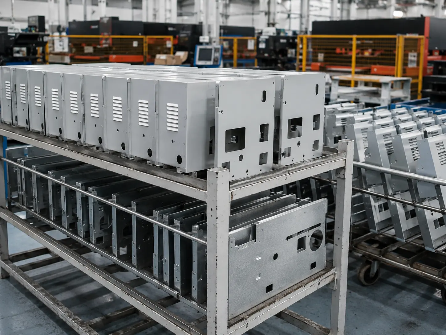
Repeat OEM sheet metal assemblies and chassis components

リピートOEMアセンブリ

ブラケット、サブアセンブリ、シャーシ部品、リピート部品

あなたのプロジェクトが大量生産モデルに適合するかを見極める方法

(一致する項目が多いほど、適合度が高くなります。)

  • 1

    図面の繰り返しが多く、 長期的な継続供給

  • 2

    が必要

  • 3

    改訂が安定しており、設計変更が少ない 単価に敏感で 治具/取付具を活用して長期的なコスト削減(スケールメリット)を受け入れる意思がある

  • 4

    高い 互換性 とアセンブリ間の一貫性が求められる

  • 5

    段取り替えが少なく、より安定した生産サイクルが必要—ライン型組織に適しています
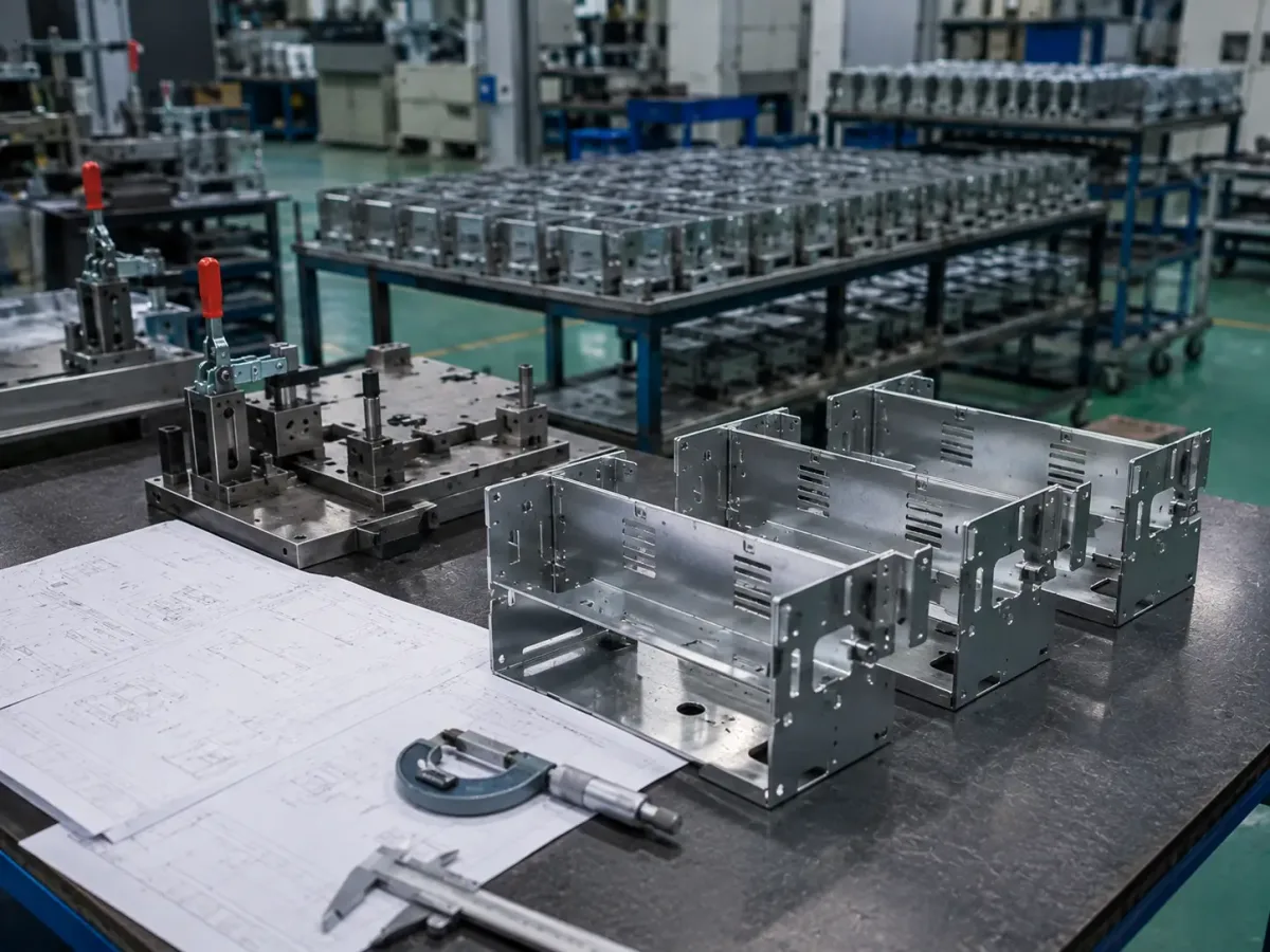
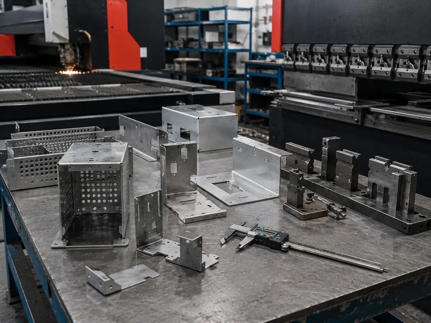
Repeat sheet metal parts, fixtures, and drawings used to evaluate high-volume production readiness
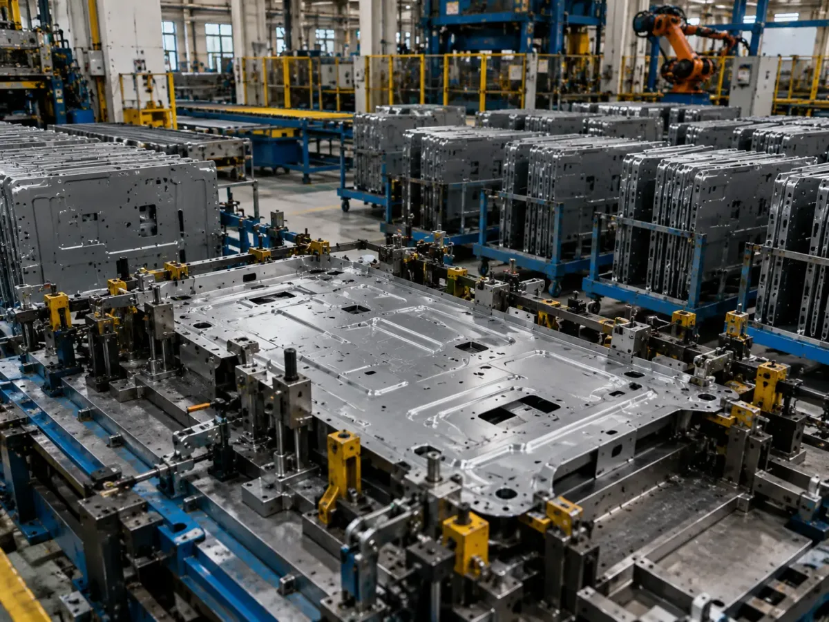
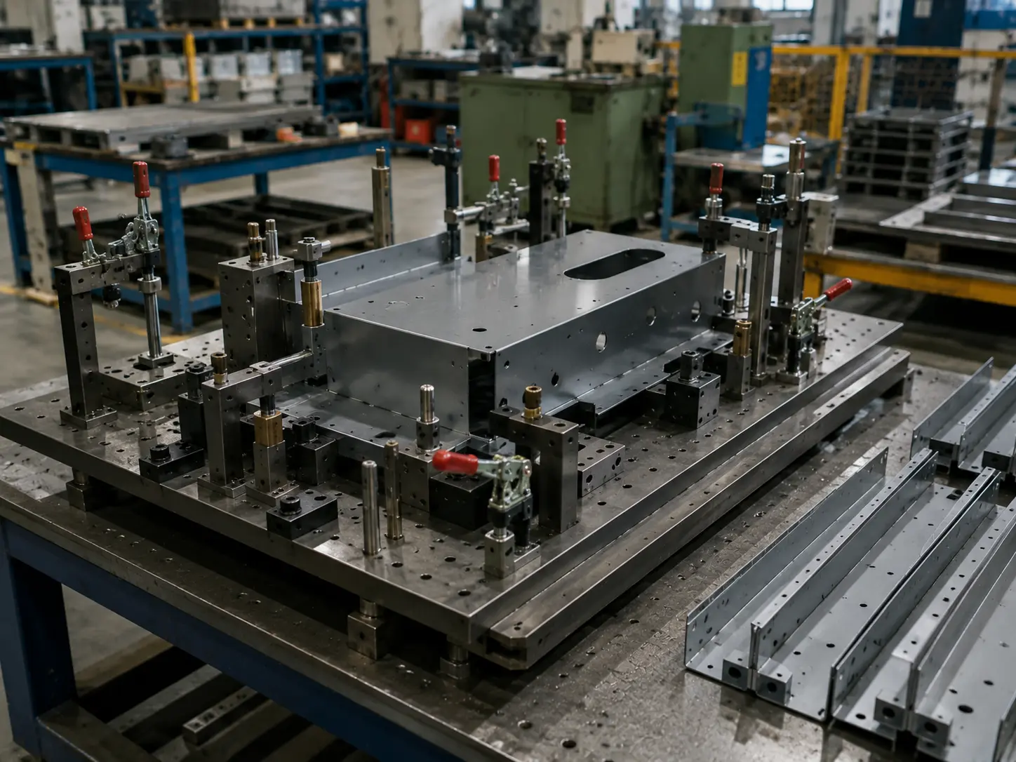
Sheet metal part positioned in dedicated tooling for repeatable high-volume production

これらのプロジェクトが大量板金生産に適する理由

スケールアップは「数量を積み上げる」ことではなく、 事前に不確実性を排除することにあります:

改訂を凍結 → CTQ(品質上重要な特性)を定義 → 治具/取付具/金型で主要データムを固定 → 反復可能なサイクル(タクト)に工程を標準化—これにより、生産量の増加に伴い、スループットの向上と単価の低減を一貫して実現できます。.

どのように選択しますか 最適な
生産プロセスルートを

年間生産量、CTQ(品質上重要な特性)、改訂頻度に基づいて製造ルートをご提案します。.

1

活発な改訂サイクル中

レーザー切断/CNCタレットパンチング+プレスブレーキ成形の柔軟なルートを使用。.

頻繁な改訂と迅速な検証に最適。.

2

ランプアップ期間中

専用治具とワークセルを導入し、タクトタイムと一貫性を早期に確立。.

3

設計が凍結され、需要が安定したら

プレス加工、ロール成形、深絞りなどの高スループットルートを評価し、単価を低減。.

生産ルート比較

生産ルート 一般的な工程構成 最適な生産段階 初期投資
(金型/治具)
単価プロファイル 主要な設計/工程上の制約
柔軟
ルート
レーザー/CNCタレットパンチ+曲げ+汎用溶接/組立 少量から中量生産;頻繁な改訂 工程数が増えると単価が急速に上昇 穴と曲げのルール、公差の累積、溶接ひずみ;外観の一貫性には治具サポートが必要なことが多い
セミツールド
ルート
CNCタレットパンチ(成形含む)/レーザー+専用治具+セルベース組立 中量から大量生産;安定した構造 中量生産 より安定した生産サイクル;コストは長期的に低減可能 CTQはより早い段階で確定する必要がある;治具戦略が再現性の上限を決定する
プレス加工
ルート
ブランキング/成形金型 + 二次曲げ/タップ/セルフクリンチング 大量生産;長期的に安定した設計 最低単価;最速スループット 変更は高コストかつ低速;DFMは事前に堅牢である必要がある
ロールフォーミング
ルート
ロールフォーミング + パンチング / カットオフ 大量生産における長尺・直線・一定断面形状部品 優れた単価経済性;非常に高い生産能力 断面形状が確定すると変更は困難;初品検証は徹底的に行う必要がある
深絞り
ルート
深絞り / 成形 + トリミング / ピアス ボウル/カップ/ハウジング型部品 深いキャビティに効率的;高いスループット 材料の成形性が重要;しわ/割れリスク;金型トライアウトと調整の時間を確保

治具戦略と生産経済性

治具なし / 最小限

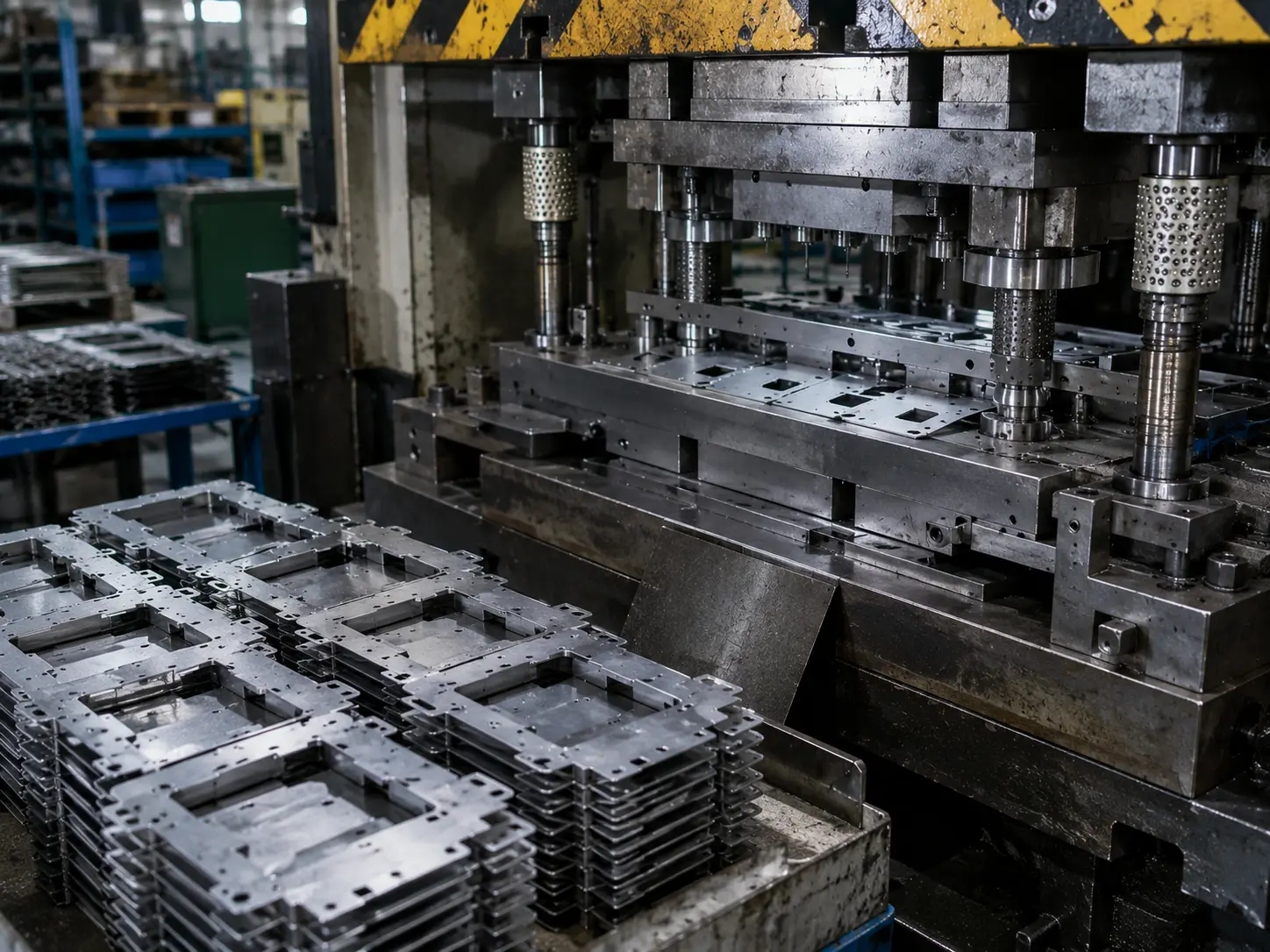
Sheet metal parts produced with minimal dedicated tooling

試作および少量生産に最適。.

ソフトツーリング

Soft tooling used for medium-volume sheet metal production

比較的短いリードタイムで低投資。.

低投資
高単価
高投資
最低単価

CTQ管理と品質一貫性

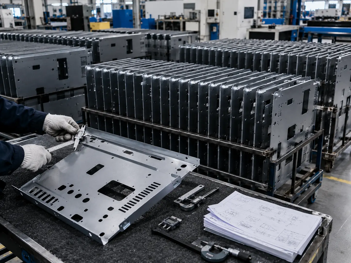
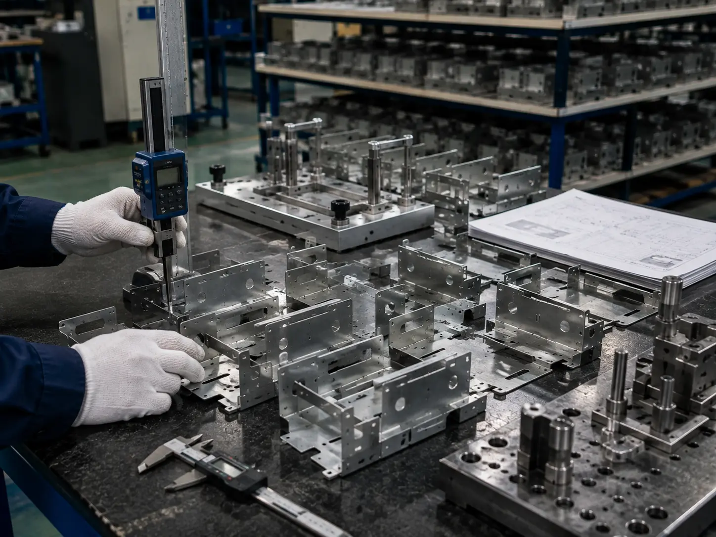
Dimensional inspection of high-volume sheet metal parts during CTQ quality control

主要CTQパラメータ

曲げ角度 通常 ±0.5°
穴位置 ±0.10 mm
平坦度 5 mm / 500 mm
エッジ状態 仕様に基づくバリ取り
表面処理 指定通り
外観 傷・打痕管理
受入材料
検証
工程内
検査
最終寸法
検査(FAI)
バッチトレーサビリティ
および記録

コスト内訳と実践的なコストダウンパス

量産プログラムでは、単価は単一の工程で決まるものではない。以下によって形成される: 材料, サイクルタイムと工数, 二次加工/外観手直し, 仕上げ要件, 、および 治具/金型投資. 。当社のアプローチは、まずコスト構造を分解し、その後、実際に実行可能な段階的コスト削減ロードマップを提案することです。DFM(設計段階での製造性検討)は、早期に適用することでコストと手直しを削減するための重要な手段です。.

大量生産向け板金製造 よくある質問 

大量生産とは単なる数量ではなく、プログラムが以下に移行した状態を指します: 長期的な反復供給:同一部品が継続的に生産され、生産サイクルが再現可能であり、初期セットアップ/金型費用を製品ライフサイクル全体で償却できる状態です。多くの業界では、, 数百から数千個の反復部品 が一般的な大量生産の目安であり、通常は 柔軟性が低く しかし 数量拡大に伴い単価が低減.

以下のトリガーのいずれかに該当した時点で、治具/金型の評価を開始することを推奨します:

  • 需要が以下に移行した場合: 安定したローリングフォーキャスト (単発受注ではない)、かつ製品ライフが初期投資を正当化できる十分な長さであること。.

  • CTQ(品質上重要な特性) が明確に定義され、設計変更が減少していること—これにより、主要なデータムや主要工程を治具や金型で「固定」できます。.

  • 単価が以下に大きく影響される場合: サイクルタイム, 、複数の工程を高スループットのフローに統合する価値が生じます(例:1回のプレスストロークで複数の形状を同時成形)。.

当社は、年間数量、ライフサイクル、設計凍結レベル、CTQ、タクト/サイクルタイム目標に基づいて、金型ベースのルートが妥当かどうかを評価します—単一の「閾値」を強制することはありません。“

根本的に、「損益分岐点」は以下によって決まります: 一時投資(金型/治具/セットアップ) がライフサイクル数量で償却可能かどうか—および 単位工数/サイクルタイム/二次加工が工程統合により大幅に削減できるかどうか。大量生産ルートは通常、セットアップ/金型費用が高くなりますが、単価は低くなります—そして通常、柔軟性は低くなります。.

当社は通常、5つの変数を検討します:

  • 償却計算: 金型/治具投資 ÷ 予測数量(製品ライフサイクル全体)

  • 工程統合: 順送/トランスファーセットアップにより、穴あけ/成形を統合し、サイクルタイムと工数を削減できます(ただし柔軟性は低下)

  • 段取り替え効率(SMED): 段取り替えを「数十分」から「数分」に短縮することで、OEEと多品種対応能力に直接影響

  • 材料歩留まりとスクラップ構造: ネスティング/レイアウトとスクラップパターンが材料コストを大きく変動させる可能性

  • CTQと公差チェーン: 敏感な特性が多いほど(穴と曲げの関係、複数曲げの積み上げ、組立データム)、治具/金型で主要な関係を「固定」する価値が高まります—またはより現実的な公差範囲を定義することも重要です。

はい—3D(STEP/IGESなど)から初期ルート推奨と概算見積範囲を提示できます。ただし、実行可能な生産見積と再現性の整合には、公差、データム、外観要件、工程注記を明確にするため、2D/PDFの追加を強く推奨します。.

最低限、以下をご提供ください:

  • 材料: 仕様/規格+板厚+表面状態

  • 公差体系: 一般公差(例:ISO 2768)+別途指定のCTQ(穴パターン、穴と曲げの関係、機能面)

  • 工程と後処理: welding / inserts / self-clinching hardware / finishing + masking areas

  • Volumes & ramp plan: first build quantity + annual rolling forecast + split-shipment cadence (this drives the process route and tooling strategy)

We recommend aligning on cosmetic grading + standardized acceptance rules:

Cosmetic surface grading

  • A: frequently seen / touched

  • B: visible

  • C: non-visible

Texture / grain direction

  • Specify brushed/grain direction clearly and keep it consistent with viewing and assembly orientation.

Color alignment

  • Use RAL / Pantone / a physical color chip, and agree on viewing conditions (light source, distance, angle). If your system requires tighter control, define an instrumented metric such as ΔE as the acceptance basis.

We prefer CTQs to be defined with datums + a clear measurement method, and flagged as CTQ in the 2D drawing for centralized control.

Recommended callouts:

  • Locating hole patterns: use a datum scheme and define positional relationships (GD&T-style) instead of stacking linear dimensions.

  • Hole-to-bend / across-bend dimensions: state which datum face/edge the measurement is taken from after forming, and distinguish single-bend vs. multi-bend chains (multi-bend stacks compound more easily).

Quick “communication anchors” (for early alignment, subject to review):

  • Bend angle often uses ±1°, cutting features often ±0.2 mm (tighter requires review).

  • Across a single bend: ±0.3 mm; across multiple bends: ±0.5 mm (review-dependent).

It depends on your current route:

Flexible route (laser/turret + bending)

  • Changes are typically handled via program updates—ideal during active iteration before the design is frozen.

Tooling-based route (single-op dies / progressive / transfer)

  • Changes may require die modification and re-tryout, which is more expensive and slower. In practice, we recommend:

    • Freeze assembly hole patterns, datum holes, and key formed features before committing to hard tooling/progressive dies.

    • For “likely-to-change” features, consider modular design areas, or a hybrid approach (stamping + secondary ops) to balance cost and takt time.

    • If frequent changes are expected, stay on laser+bending longer, or use stamping with secondary machining for the moving features.

Yes. To prevent rework and assembly variation at volume, we typically need:

  • Hardware/insert list: part numbers, material/finish, quantity, install side, hole requirements, and install direction

  • Assembly information: assembly drawing/exploded view, key clearances, torque requirements, and acceptance criteria (pull-out/spin-out, if applicable)

  • If blind rivets are involved, we can align to the applicable ISO standard (for example, ISO 15977 covers open-end blind rivets with a break-pull mandrel)

We propose alternatives in this priority order: same function → manufacturable → controlled risk:

  • Closest-grade substitutions within the same family (protecting key needs like corrosion resistance, conductivity, magnetism)

  • Standardized thickness/width to improve availability and nesting yield

  • If needed, thickness/structure compensation (local flanges, ribs) to maintain strength and interfaces

  • After substitution, we recommend a small validation build to confirm forming/springback, finishing compatibility, and assembly performance.

In one line: finishes add build—critical fits should be masked or designed with allowance.

  • Powder coating: typical film build is about 2–5 mil (50–125 μm), which can noticeably affect holes, slip fits, and snap features

  • Anodizing: as a conversion coating, it has dimensional growth both inward and outward (not purely “added on top” like plating)

Recommendation: call out in your 2D notes:

  • finish areas

  • masking areas

  • post-finish requirements for critical fits (holes/threads/grounding surfaces/EMI shielding interfaces)

Yes—and it’s a common, low-risk path for high-volume programs:

  • Phase 1 (validation): laser/turret + bending + only necessary fixtures to validate assembly and CTQs

  • Phase 2 (ramp): key fixtures + cell-based organization to lock takt time and consistency

  • Phase 3 (stable high output): once the design is frozen and demand is stable, evaluate single-op / progressive / transfer dies

This staged-investment approach reflects the basic reality of high-volume manufacturing: setup costs are higher, but can be amortized over a long, stable lifecycle—without betting on hard tooling before the design is truly frozen.