双瑞と提携して製造コストを削減 30% 効率を向上させます.

レーザー切断サービスOEM2026-08-13T09:23:45+00:00

OEM金属部品向けカスタムレーザー切断サービス

SR MFGは、カスタム板金部品、筐体、パネル、ブラケット、フレーム向けの精密レーザー切断を提供しています。試作からバッチ生産まで対応し、クリーンな切断面、高精度なプロファイル、安定した再現性を実現します。.

±
±0.03 mm/m
位置決め精度
1500 × 3000 mm
最大板材サイズ
OEM
試作・バッチ生産
生産サポート

24時間以内にカスタム見積もりを取得

図面をアップロードしてエンジニアリングレビューを受けてください。.

空白フォーム (#4)

カスタムレーザー切断でSR MFGが選ばれる理由

OEMレーザー切断および板金製造プログラムの信頼できるパートナー。.

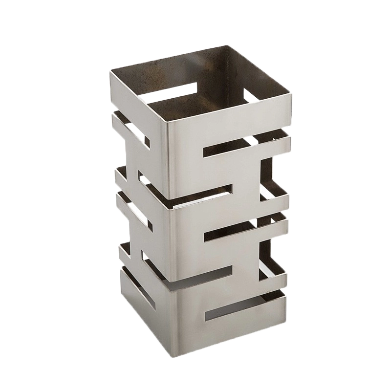
Stainless steel laser cutting parts

高精度切断

±0.03 mm/mの位置決め精度により、精密なプロファイルと複雑な形状に対応します。.

安定した切断品質

高度なビーム制御とリアルタイムモニタリングにより、クリーンな切断面と安定したHAZを実現し、ばらつきを最小限に抑えます。.

大型フォーマット対応

1500 x 3000 mmの大型板材サイズにより、幅広いパネル、筐体、構造部品に対応します。.

多素材切断

炭素鋼、ステンレス鋼、アルミニウム、銅、亜鉛メッキ鋼板などを安定した品質で切断します。.

SR MFG vs. 一般的なレーザー切断サプライヤー

切断能力、精度、生産能力、リードタイム、ワンストップ製造サポートの実用的な比較。.

項目 SR MFGの優位性 一般的な競合他社
切断能力 幅広い板厚範囲に対応する多素材切断 対応素材や板厚が限定的
精度・品質 先進設備によるクリーンな切断面と安定した品質 設備やオペレーターにより精度が変動
生産能力 複数台の設備による並列生産対応 バックアップ能力が限定的
リードタイム 迅速な試作品とスケーラブルなバッチ生産 大口注文ではリードタイムが長期化
ワンストップ製造 切断、曲げ、溶接、表面処理、組立 レーザー切断のみ
品質保証 ISO認証プロセスと検査管理体制 認証取得が少なく、QC体制が未整備
コスト効率 サプライチェーンリスクの低減とプロジェクト管理の向上 分断されたサプライチェーンと高い失敗リスク
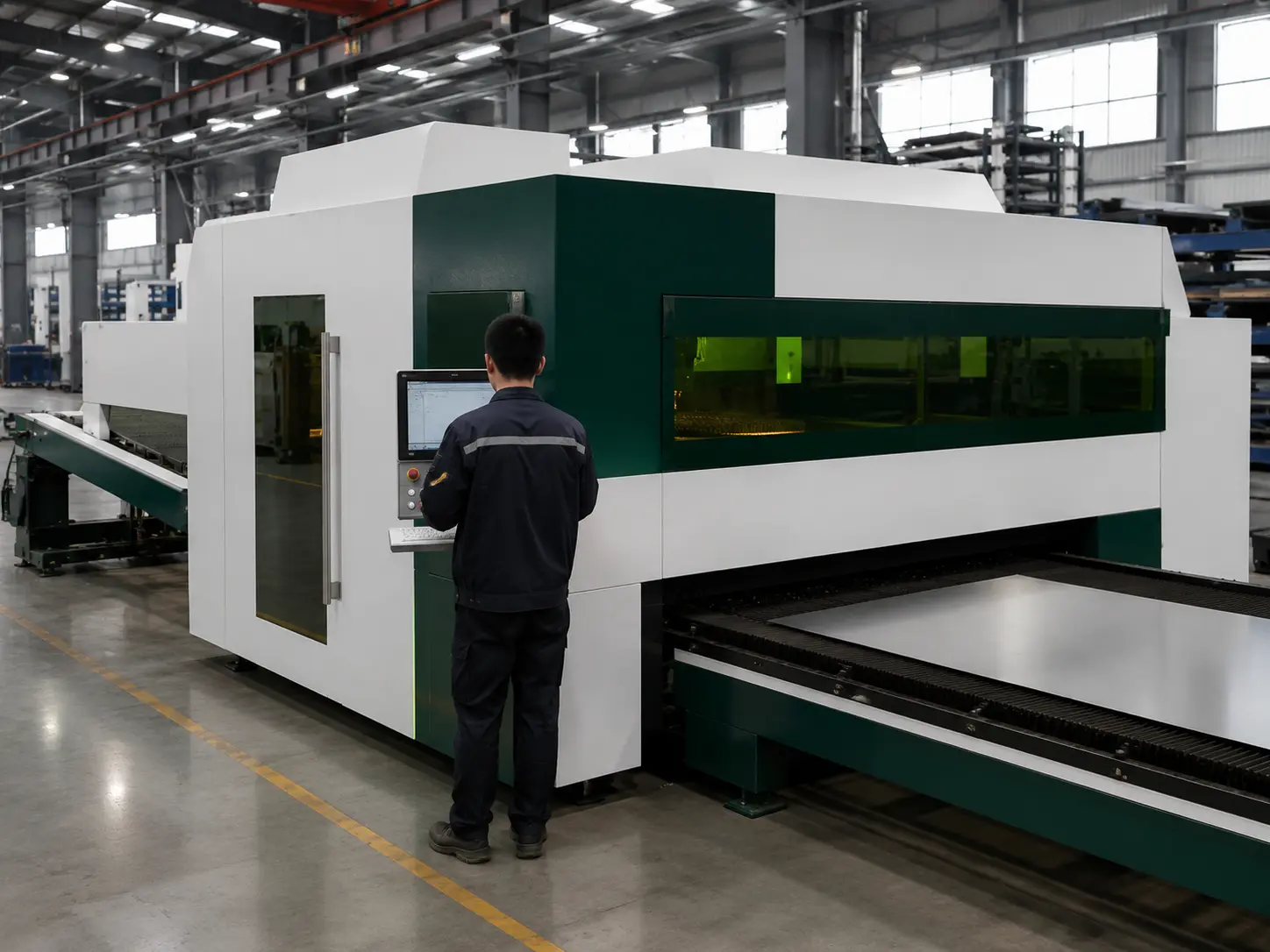
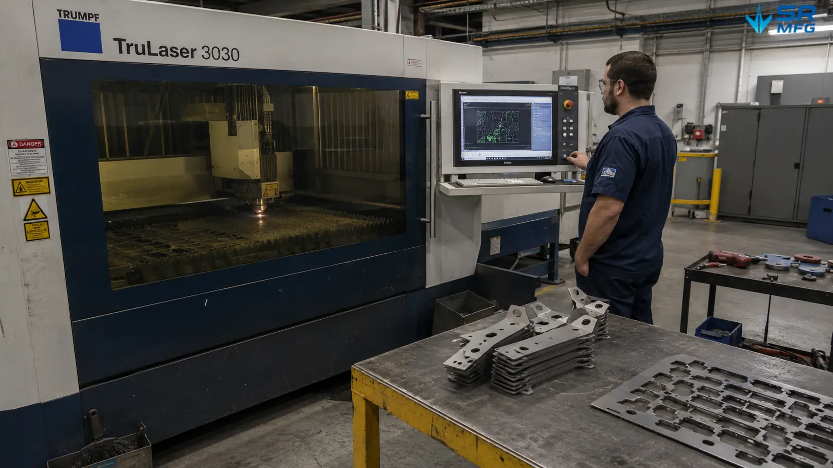
Fiber laser cutting machine cutting steel bracket parts through the protective viewing window, with an operator monitoring the cutting program on the HMI control panel
能力

SR MFGの精密レーザー切断能力

SR MFGは、カスタム板金部品、エンクロージャー、パネル、ブラケット、フレーム向けの精密レーザー切断を提供しています。.

制御された切断パラメータと自動化生産設備により、試作からバッチ製造まで対応し、クリーンな切断面と安定した再現性を実現します。.

クリーンな切断面品質

バリ、変形、二次仕上げ作業を低減します。.

複雑な形状の切断

スロット、穴、輪郭、カスタム板金プロファイルを切断します。.

反射性金属の切断

アルミニウム、銅、真鍮、その他の反射性金属に対応しています。.

材料歩留まりの最適化

ネスティング効率を向上させ、板金の無駄を削減します。.

信頼されるOEMパートナー

先進のレーザー切断設備、厳格な工程管理、ISO認証の品質マネジメントにより、すべてのプロジェクトで一貫した性能と長期的な信頼性を保証します。.

SR MFGのレーザー切断機の種類

CO₂レーザー切断機

CO₂レーザー切断機

板金業界の大半はファイバーレーザー切断に移行していますが、CO₂システムは特定のケース——例えば厚さの変動が大きい部品、非金属サンドイッチ構造、異種材料の試作品——において今なお重要な役割を果たしています。当社のCO₂レーザー切断システムは、安定した切断品質と一貫した切断面性能が求められる金属板加工に使用されています。特殊な材料特性に合わせた再設計を必要とせず、滑らかなエッジ遷移と精密なディテールを実現します。.
ファイバーレーザー切断機

ファイバーレーザー切断機

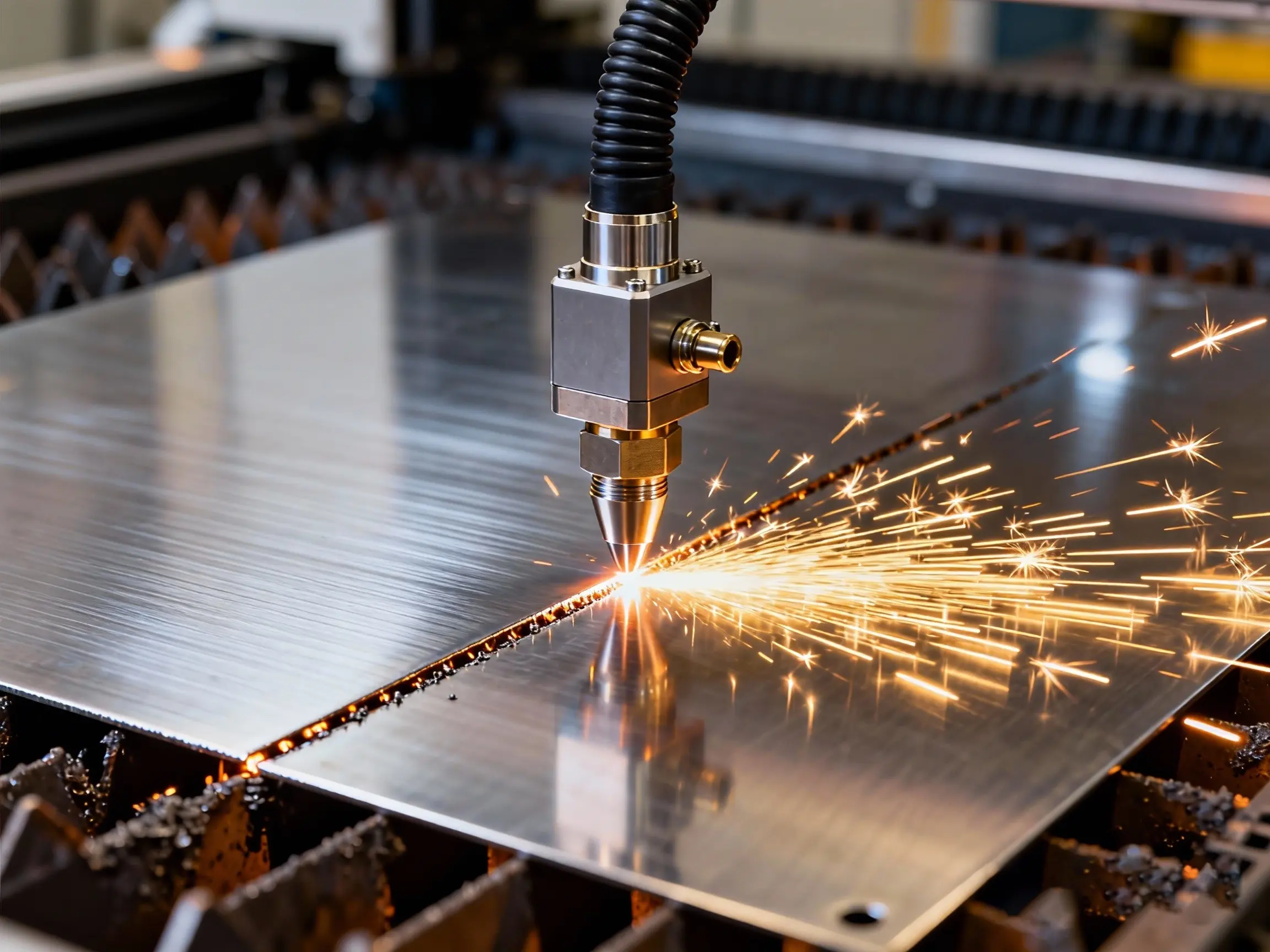
SR MFGのファイバーレーザー切断機は、反射性材料を含む大量生産およびカスタム金属部品の両方に対して、効率的で高速な切断を実現します。3~5 kWの出力と自動搬入・搬出およびラッキングにより、当社のラインは安定した速度、再現性のある精度、一貫したビーム品質を維持します——無人運転や少人数運用においても、真の生産性は出力だけでなく安定性から生まれます。.

当社のレーザー切断設備

SR MFGは、さまざまな板金材料、板厚、部品サイズ、生産量に対応するため、複数のレーザー切断システムを使用しています。.
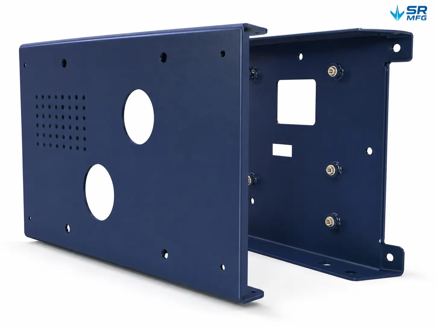
主要レーザー切断システム
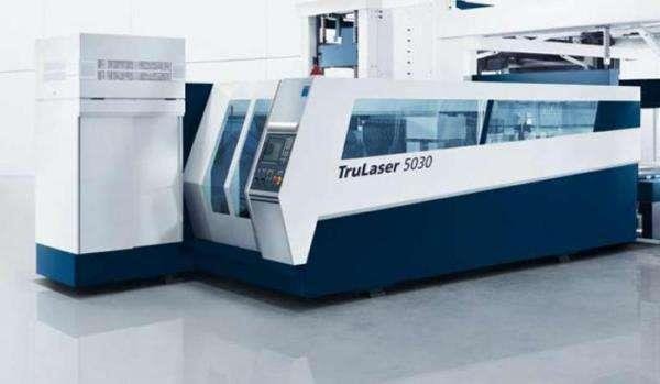
トルンプ TruLaser 5030

大判板金部品および厚板用途向けに設計された高出力精密切断システム。.

  • 大判切断
  • 高出力安定性
  • 構造部品対応

トルンプ TruLaser 4030

さまざまな材料と板厚にわたって安定した切断面品質を実現する汎用CO₂レーザー切断システム。.

  • CO₂レーザー技術
  • 一貫した切断面品質
  • 異種材料対応
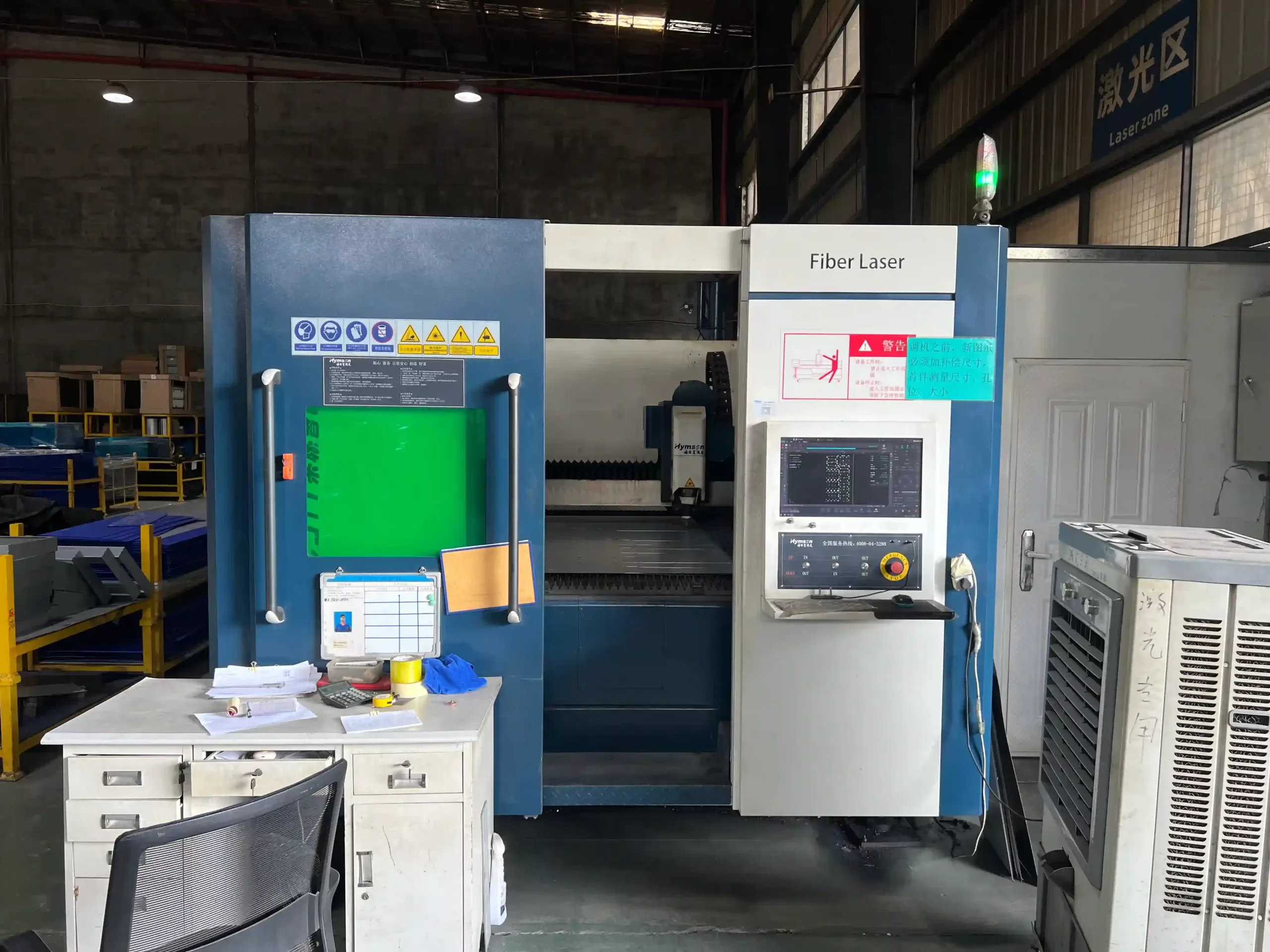
ハイムソン HF3015B

ハイムソン HF3015B

薄板加工、バッチ生産、短納期に最適化された信頼性の高いファイバーレーザー切断システム。.

  • 薄板切断
  • コスト効率の高い運用
  • バッチの短納期対応
  • 機械の選定は、材料、板厚、公差、形状、受注量によって異なります。.

詳細な設備仕様

レーザー出力、作業テーブルサイズ、切断板厚、精度、搬入対応。.

設備モデル レーザー種類/出力 作業テーブル 最大切断板厚 位置決め精度 再現精度 自動搬入
トルンプ TruLaser 5030 ファイバーレーザー/5 kW 3000 × 1500 mm 25 mm carbon steel / 20 mm stainless steel ±0.03 mm/m ±0.02 mm Supported
トルンプ TruLaser 4030 CO₂ Laser / 4 kW 3000 × 1500 mm 20 mm carbon steel ±0.03 mm/m ±0.02 mm Supported
ハイムソン HF3015B Fiber Laser / 3 kW 3000 × 1500 mm 20 mm carbon steel ±0.03 mm/m ±0.02 mm Supported

Production Capacity Benchmark

Internal capacity reference based on continuous production conditions.

Reference condition: 6 mm carbon steel · Continuous 24-hour, 3-shift operation.
設備モデル Cutting Speed Utilization Rate Daily Output
(Theoretical Cutting Length)
Typical Part Qty
(per day, based on 1m × 1m sheet parts)
TruLaser 5030 30 m/min 85% 36,720 m ~3,600 parts
TruLaser 4030 15 m/min 85% 18,360 m ~1,800 parts
HF3015B 25 m/min 85% 30,600 m ~3,000 parts
Total daily capacity: over 9,000 thin-sheet parts/day. Actual output depends on part complexity, material thickness, nesting efficiency, material changeover, and machine warm-up or maintenance.

Accuracy, Tolerance & Repeatability

SR MFG focuses on stable,consistent quality in mass production. Our laser cutting process ensures
tight tolerances, smooth edges, and excellent repeatability from prototype to large-scale production.

±0.10 mm

Mass Production Tolerance
Consistent tolerance for mostsheet metal parts.

±0.03 mm/m

Positioning AccuracyHigh positioning precision ensuresexcellent dimensional control.

Standard Tolerances for Laser-Cut Metal

View reference tolerance ranges by machine type, thickness, accuracy, roughness, and tolerance grade.

Machine Model 材料厚さ Linear Dimensional Tolerance Angular Tolerance
(per 100 mm)
Hole Position Tolerance
(Hole Diameter ≤ 50 mm)
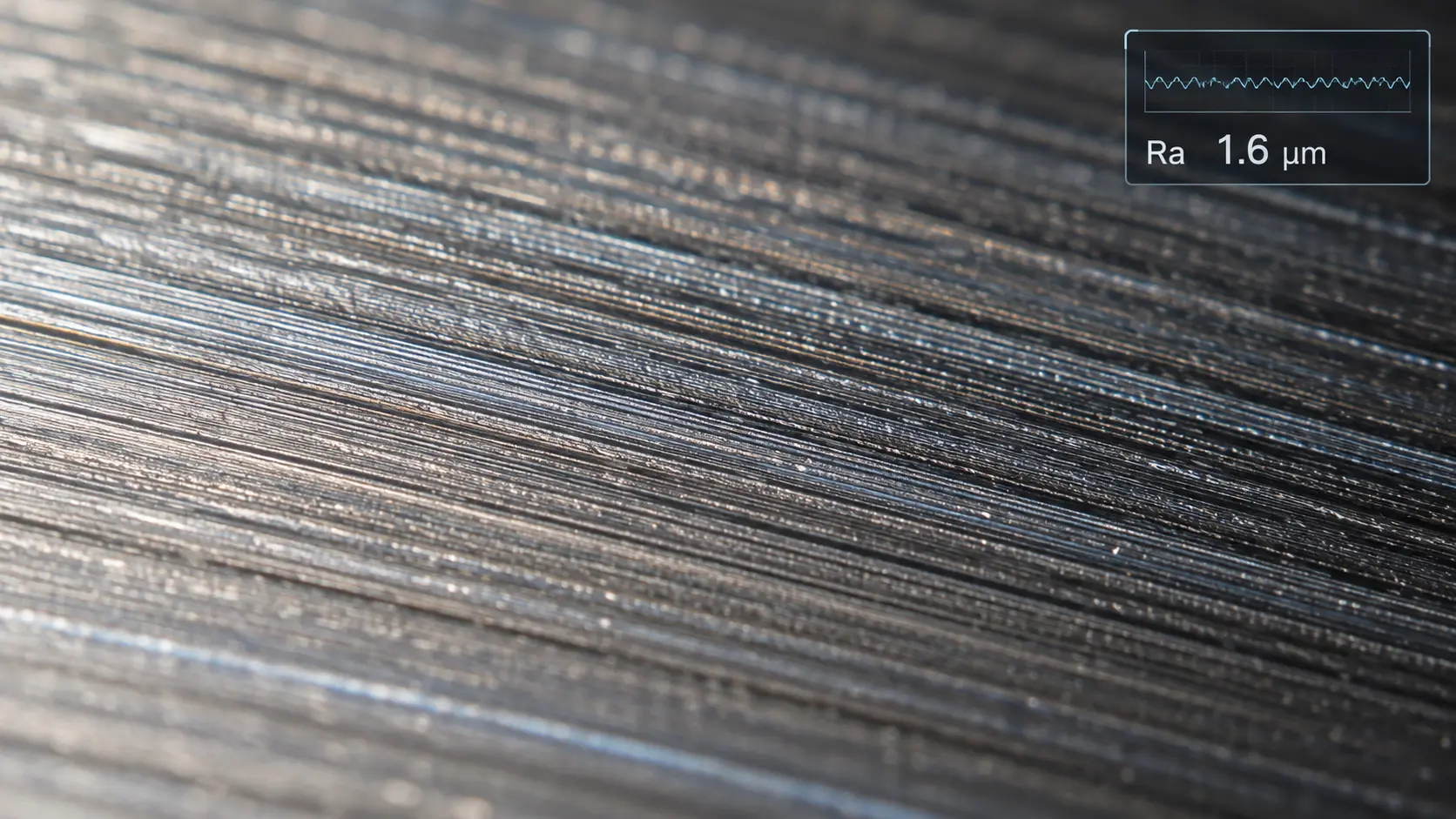
Surface Roughness Ra
(μm)
Tolerance Grade
TRUMPF 5030
(Fiber Laser)
≤ 3 mm ±0.05 mm ±0.1° ±0.05 mm 1.6–3.2 IT8
3–6 mm ±0.10 mm ±0.1° ±0.10 mm 1.6–3.2 IT9
6–12 mm ±0.15 mm ±0.1° ±0.10 mm 3.2–6.3 IT9
12–20 mm ±0.20 mm ±0.2° ±0.15 mm 3.2–6.3 IT10
> 20 mm ±0.30 mm ±0.2° ±0.15 mm 6.3–12.5 IT10
TRUMPF 4030
(CO₂ Laser)
≤ 3 mm ±0.08 mm ±0.1° ±0.08 mm 3.2–6.3 IT8
3–6 mm ±0.15 mm ±0.1° ±0.12 mm 3.2–6.3 IT9
6–12 mm ±0.20 mm ±0.2° ±0.15 mm 6.3–12.5 IT9
12–20 mm ±0.25 mm ±0.2° ±0.20 mm 6.3–12.5 IT10
> 20 mm ±0.35 mm ±0.3° ±0.20 mm 12.5–25 IT10
ハイムソン HF3015B
(Fiber Laser)
≤ 3 mm ±0.06 mm ±0.1° ±0.06 mm 1.6–3.2 IT8
3–6 mm ±0.12 mm ±0.1° ±0.10 mm 1.6–3.2 IT9
6–12 mm ±0.18 mm ±0.2° ±0.12 mm 3.2–6.3 IT9
注記: For conventional steel and aluminum thin-sheet parts, SR MFG can typically maintain mass-production tolerance around ±0.1 mm. Final tolerances depend on material, thickness, part geometry, contour complexity, and inspection requirements.

Small Holes & Complex Contours

For small holes, sharp corners, narrow slots, and complex contours, SR MFG adjusts piercing strategy, beam mode, and cutting path to maintain stable edge quality and dimensional accuracy.

  • Optimized initial piercing strategy
  • Beam mode adjustment for fine features
  • Step-cutting for complex contours
  • Micro-joints added when needed for stability
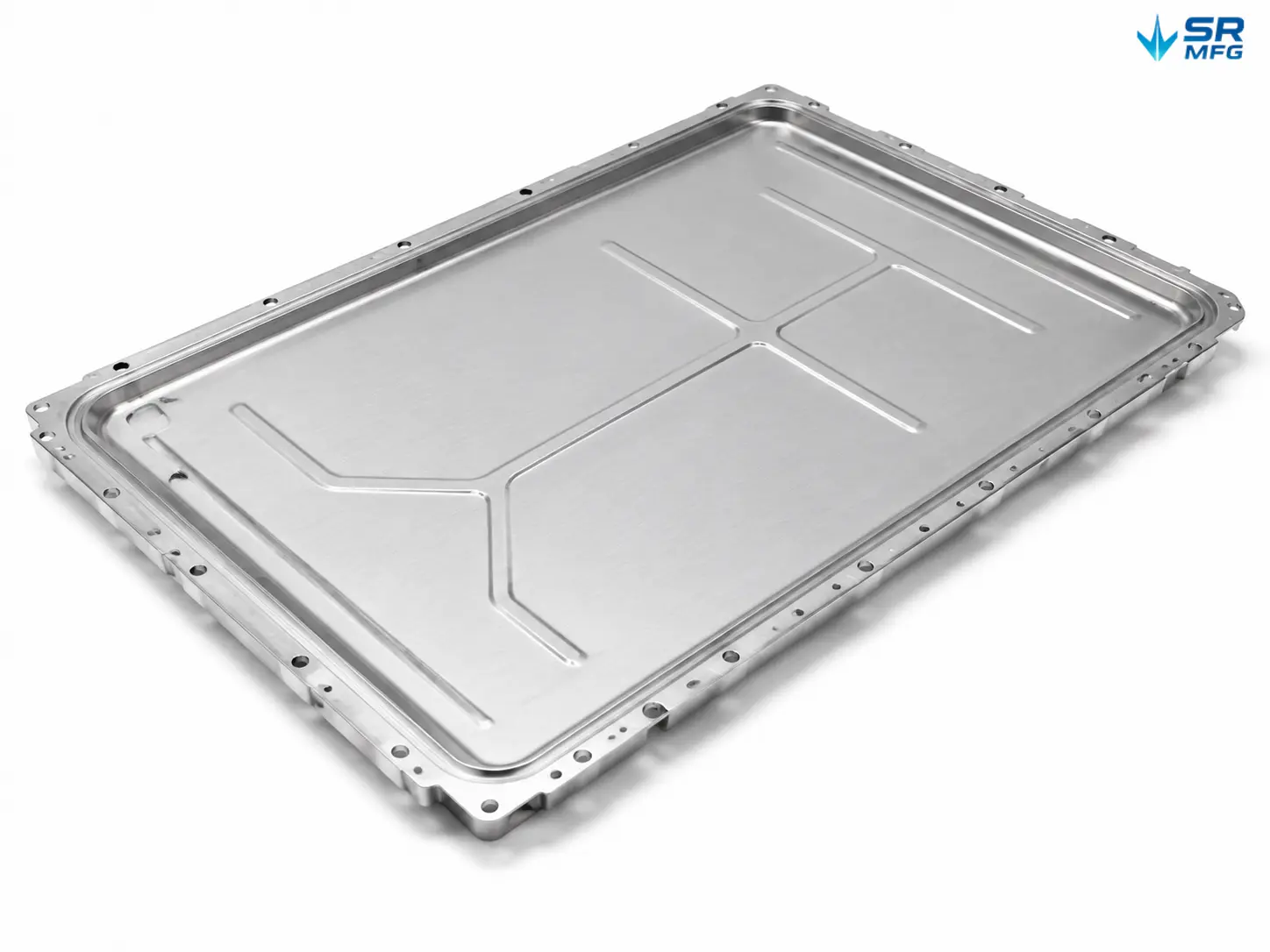
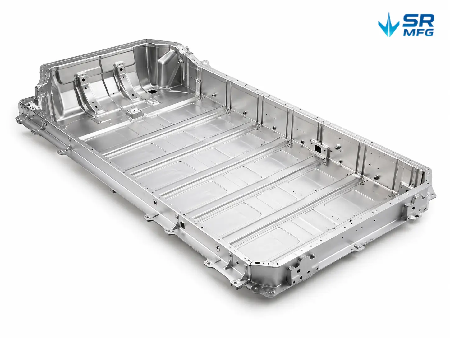
Result: Complex parts such as electronic housings, brackets, and battery trays can remain stable from prototype samples to repeat production batches.

HAZ & Edge Quality Control

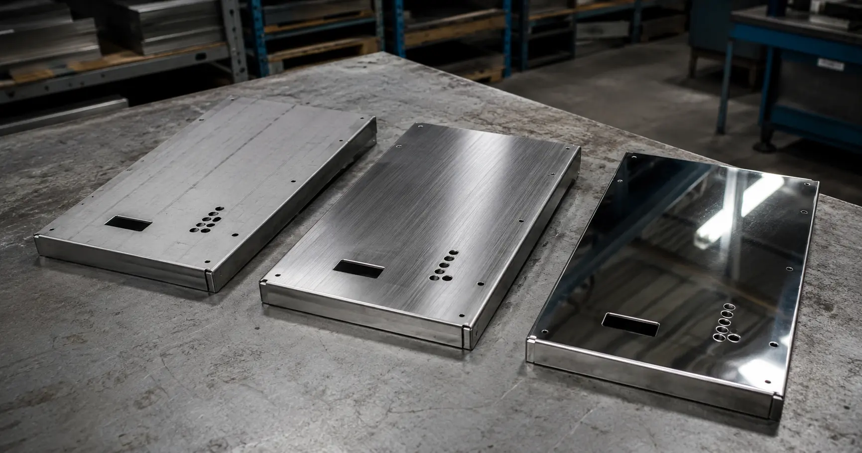
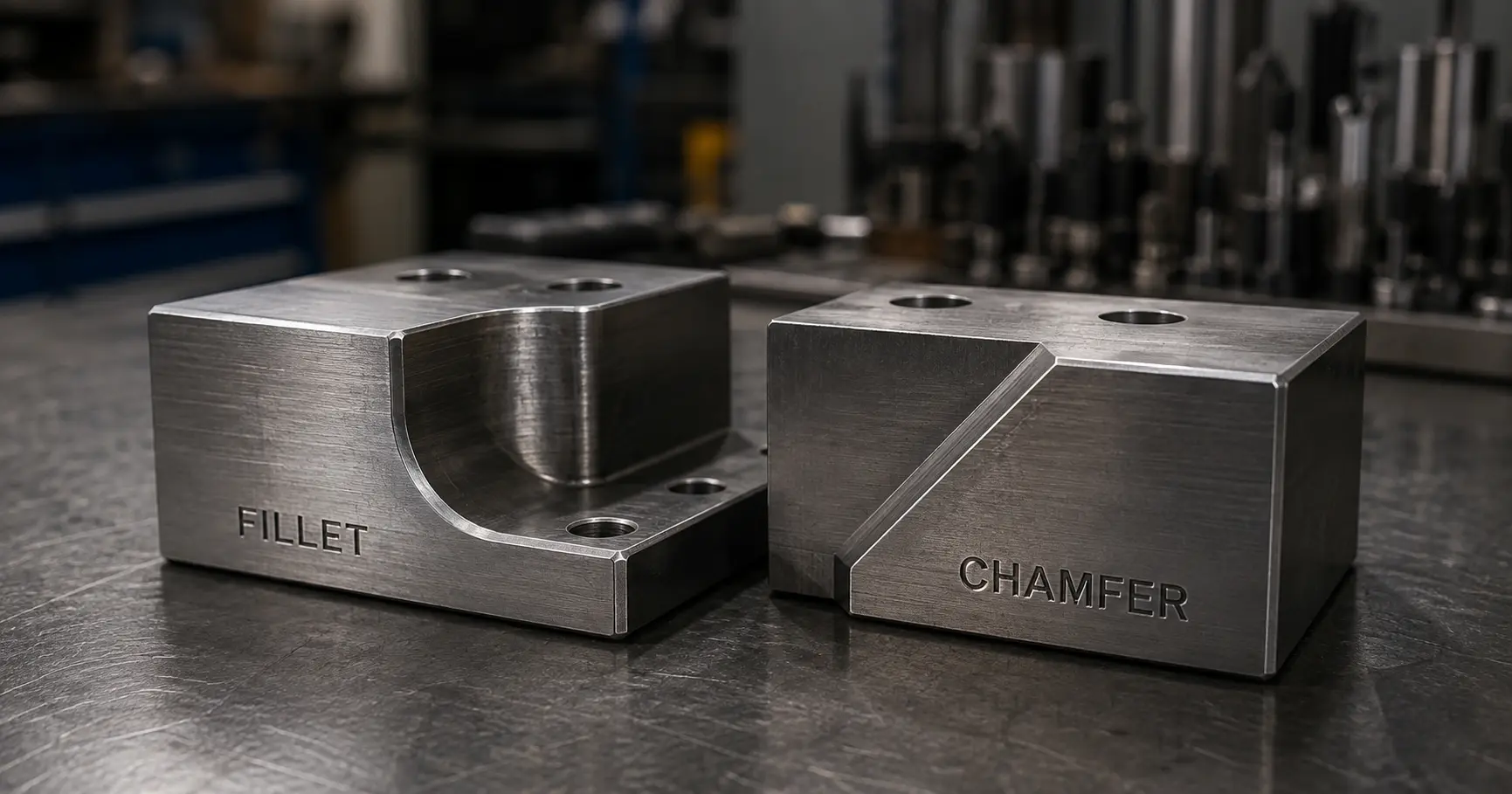
Edge quality affects later bending, welding, coating adhesion, and assembly. SR MFG controls heat input, assist gas pressure, and cutting paths to reduce burrs, overheating, and deformation.

  • Low-heat input path optimization
  • Assist gas pressure control
  • Segmented toolpaths to avoid localized overheating
  • Edge condition review before bending or finishing
Result: Parts are closer to a “ready for next process” condition, reducing heavy rework and improving overall laser cutting quality.

Repeatability & Batch Consistency

For batch production, the key challenge is not only making one accurate part, but keeping dimensions consistent across different shifts, machines, and repeat orders.

  • Standardized cutting parameters
  • Consistent sheet clamping method
  • Unified toolpath offset settings
  • Nozzle and head wear monitoring across batches
Result: Centralized process parameters help maintain dimensional consistency from prototype validation to large-volume production.
  • For special requirements or tighter tolerances, contact our engineering team. We willreview feasibility and provide the best solution

From Prototype to Mass Production

SR MFG supports laser-cut sheet metal projects from rapid samples to repeat batch production.
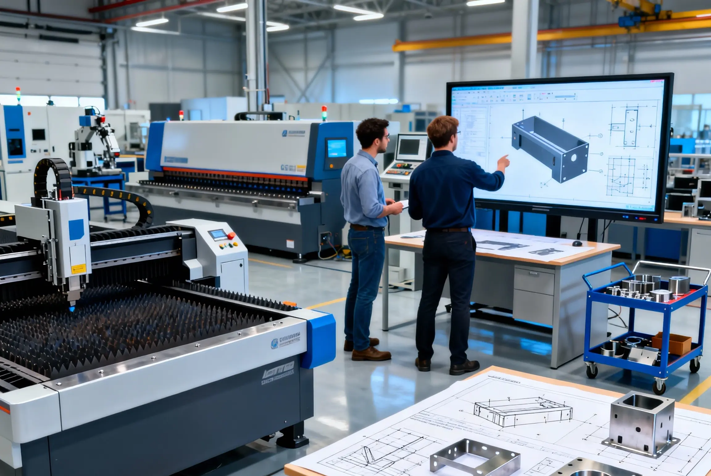
Prototype Rapid Sample Lead Time

Prototype Samples

Rapid samples for fit, function, anddesign validation.

  • 3-7 day sample lead time

  • DFM review and program setup

  • Sample validation and quick feedback

Mass-Production Capability

Small & Medium Batch

Flexible batch production forvalidated sheet metal parts.

  • 100-5,000 pcs typical range

  • Standard process parameters

  • Controlled inspection and fast changeover

SR MFG's production volume range for laser-cut parts 1 piece →100,000+ pieces

量産

Repeatable production with controlled quality and delivery.

  • 5,000-100,000+ pcs capability

  • Multi-machine capacity

  • Batch traceability and process control

Common Laser Cutting Materials & Grades

SR MFG supports stable, mass-production-ready laser cutting for commonly used sheet metal materials. If you are not sure which grade is suitable, our team can recommend the right material based on thickness, performance, and application requirements.

Carbon Steel and Low Alloy Steel

Batch cutting thickness: 3–20 mm

Maximum cutting thickness: 22 mm
Assist gas: Oxygen
Typical applications: Building structural parts, equipment bases

View Q235/B carbon steel guide →

Batch cutting thickness: 3–18 mm

Maximum cutting thickness: 20 mm
Assist gas: Oxygen
Typical applications: Bridge brackets, factory machinery components

View hot-rolled steel guide →

Batch cutting thickness: 2–15 mm

Maximum cutting thickness: 18 mm
Assist gas: Oxygen
Typical applications: Drive shafts, gear blanks

Batch cutting thickness: 0.5–12 mm

Maximum cutting thickness: 15 mm
Assist gas: Oxygen
Typical applications: Precision electronic housings, automotive parts

View SPCC cold-rolled steel guide →

Batch cutting thickness: 0.5–10 mm

Maximum cutting thickness: 12 mm
Assist gas: Air
Typical applications: Precision electronic housings, cabinets, home appliance casings

View SGCC galvanized steel guide →

ステンレス鋼

Batch cutting thickness: 1–15 mm

Maximum cutting thickness: 18 mm
Assist gas: Nitrogen
Typical applications: Medical equipment, food machinery

View 304 stainless steel guide →


Batch cutting thickness: 1–12 mm

Maximum cutting thickness: 15 mm
Assist gas: Nitrogen
Typical applications: Marine engineering, chemical containers

View 316L stainless steel guide →

Batch cutting thickness: 1–18 mm

Maximum cutting thickness: 20 mm
Assist gas: Air
Typical applications: Decorative parts, home appliance panels

View 430 stainless steel guide →

Batch cutting thickness: 1–10 mm

Maximum cutting thickness: 12 mm
Assist gas: Nitrogen
Typical applications: Blades, valve cores

Aluminum and Aluminum Alloys

Batch cutting thickness: 1–8 mm

Maximum cutting thickness: 10 mm
Assist gas: Nitrogen
Typical applications: Fuel tanks, marine accessories

View 5052-H32 aluminum guide →

Batch cutting thickness: 1–6 mm

Maximum cutting thickness: 8 mm
Assist gas: Nitrogen
Typical applications: Mechanical frames, electronic heat dissipation parts

View 6061-T6 aluminum guide →

Batch cutting thickness: 0.5–5 mm

Maximum cutting thickness: 6 mm
Assist gas: Nitrogen
Typical applications: Appearance parts, electrical components, conductive parts

View 1060 pure aluminum guide →

Batch cutting thickness: 1–4 mm

Maximum cutting thickness: 5 mm
Assist gas: Nitrogen
Typical applications: Aerospace structural parts, drone structural components, high-strength supports

View 7075-T6 aluminum guide →

Other Special Materials

Batch cutting thickness: 1–5 mm

Maximum cutting thickness: 6 mm
Assist gas: Nitrogen
Typical applications: Electrical connectors, bathroom hardware

View H62 brass guide →

Batch cutting thickness: 1–4 mm

Maximum cutting thickness: 5 mm
Assist gas: Nitrogen
Typical applications: Busbars, heat sinks

View T2 copper guide →

Batch cutting thickness: 1–8 mm

Maximum cutting thickness: 10 mm
Assist gas: Argon
Typical applications: Structural components, connectors, frames, aircraft load-bearing parts, medical implants

View TC4 titanium alloy guide →

  • Material Compatibility Notes

To ensure consistent cutting quality and stable mass production, we use a simple compatibility guide based on tested thickness ranges for each material on our 3–5 kW fiber and CO₂ laser systems.

  • For best results, keep designs within the recommended batch-production thickness range; performance may decrease near the maximum thickness limit.
  • If your parts include small holes, sharp corners, long narrow slots or other high-difficulty features, please let us know in advance.
  • Different materials and any post-processing (bending, welding, painting, etc.) require specific process windows—share complete drawings so we can run a DFM review and set up the right workflow.

How We Control レーザー切断 Accuracy

At SR MFG, “accuracy” is a complete system of parameters, actions, and inspections—not just a nice-looking part in a single run. Our goal is to keep cutting quality stable across different times and batches.

Process Parameter Control

Laser power, cutting speed, focus position, andpiercing parameters are automatically adjustedbased on material type and thickness.

  • Material & thickness specific process window

  • Real-time monitoring and auto compensation

  • Stable cutting quality across different batches

Assist Gas Selection

Appropriate assist gas (N2 / O2/ Air) is selectedaccording to material and surface requirementsto balance edge quality and production efficiency.

  • N₂ for clean edges and oxidation-free surfaces

  • O₂ for carbon steel: faster cutting, better efficiency

  • Air for cost-effective cutting on suitable materials

Kerf & Edge Quality Control

We control kerf width, edge flatness, burr height, and heat-affected zone to ensure parts are ready for bending, welding, and assembly.

  • Typical kerf width: 0.08–0.15 mm (varies by material)

  • Low burr, smooth edge, minimal dross

  • Consistent results for tight-tolerance parts

In-Process Inspection

Key dimensions and critical features are inspected during production to catch issues early and keep quality consistent.

  • Dimensional checks (holes, slots, profiles)

  • Edge quality and burr inspection

  • First-piece & random sampling throughout the run

レーザー切断 Quality Assurance Workflow

To ensure each batch meets the same high standard, SR MFG breaks laser cutting quality control into multiple stages, with traceable data points at each phase, ensuring consistent laser cutting precision および repeatable quality. This ensures that every laser-cut part, from the first to the last, remains consistent.

DFM Review Before Laser Cutting

We don’t just “cut to print.” SR MFG works with you from CAD data to mass production, using DFM and engineering support to reduce redesigns, stabilize quality, and keep costs under control.

CO₂レーザー切断機

Upfront DFM Review
We review every CAD file for manufacturability, catching issues in holes, slots, ribs, and bend areas before the first sheet is cut.

01.Design Review

Check material, thickness, holes, slots, bend areas, and tolerance risks.

02.Prototype Validation

Use samples to verify fit, function, and process parameters before batch production.

03.Risk Control

Identify warping, burrs, tolerance stack-up, and edge-quality risks early.
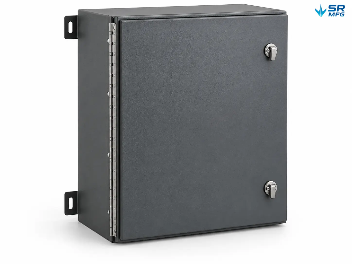
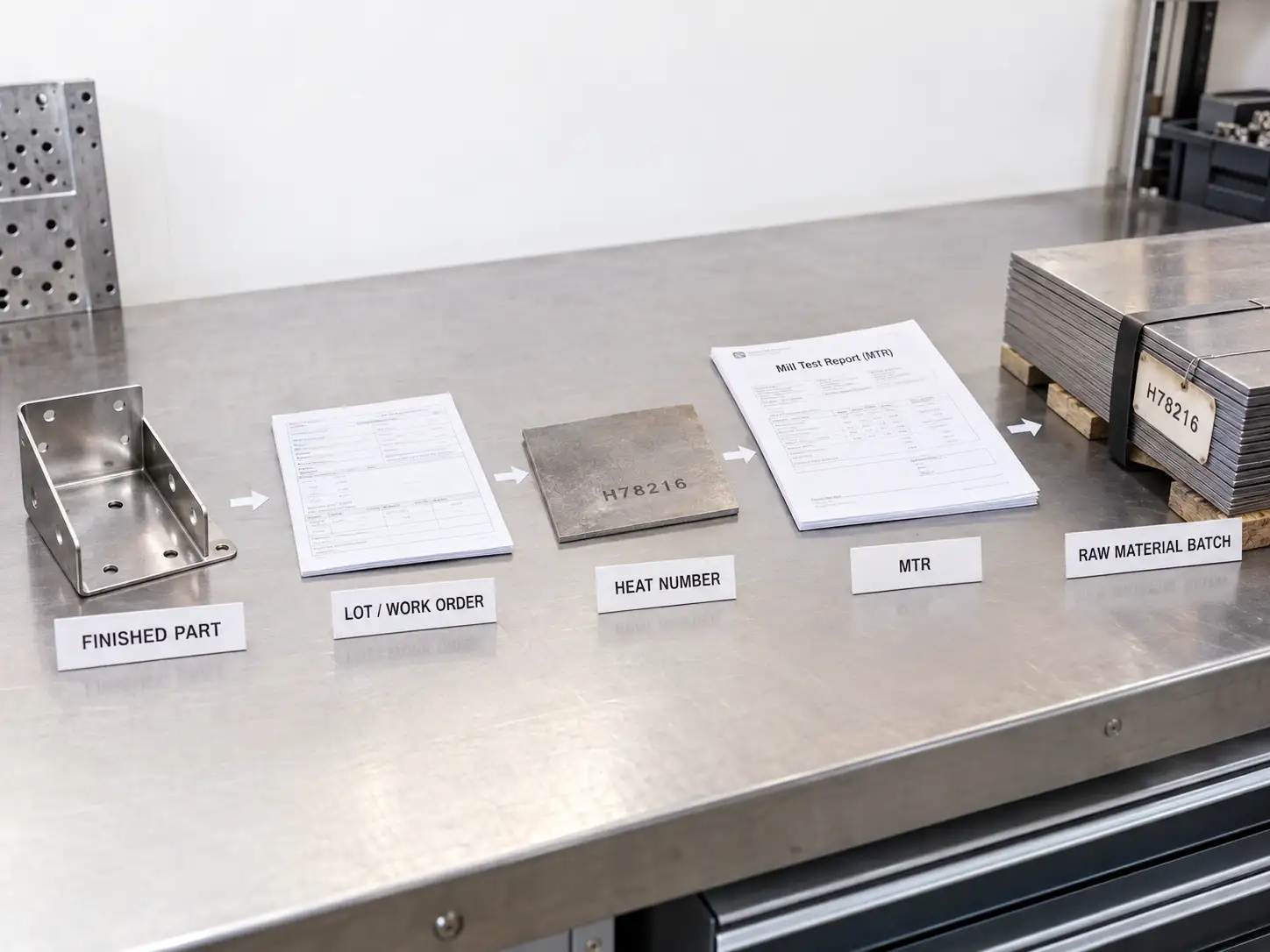
トレーサビリティ

Traceability, Certification & Compliance

Laser-cut parts not only need to meet dimensional requirements but must also form a closed-loop system in terms of material origin, process records, and export compliance. This capability is often not shown directly, but it determines the stability of the supply chain—especially in highly consistency-driven industries such as new energy, data centers, electrical control cabinets, industrial computers, medical equipment, and telecommunications.

The following sections describe our structured approach to traceability and compliance systems.

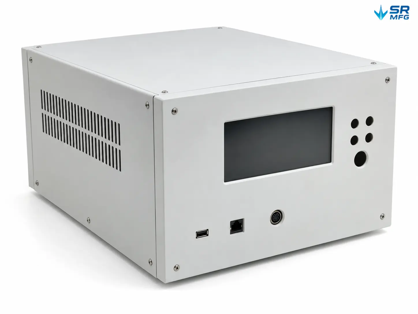
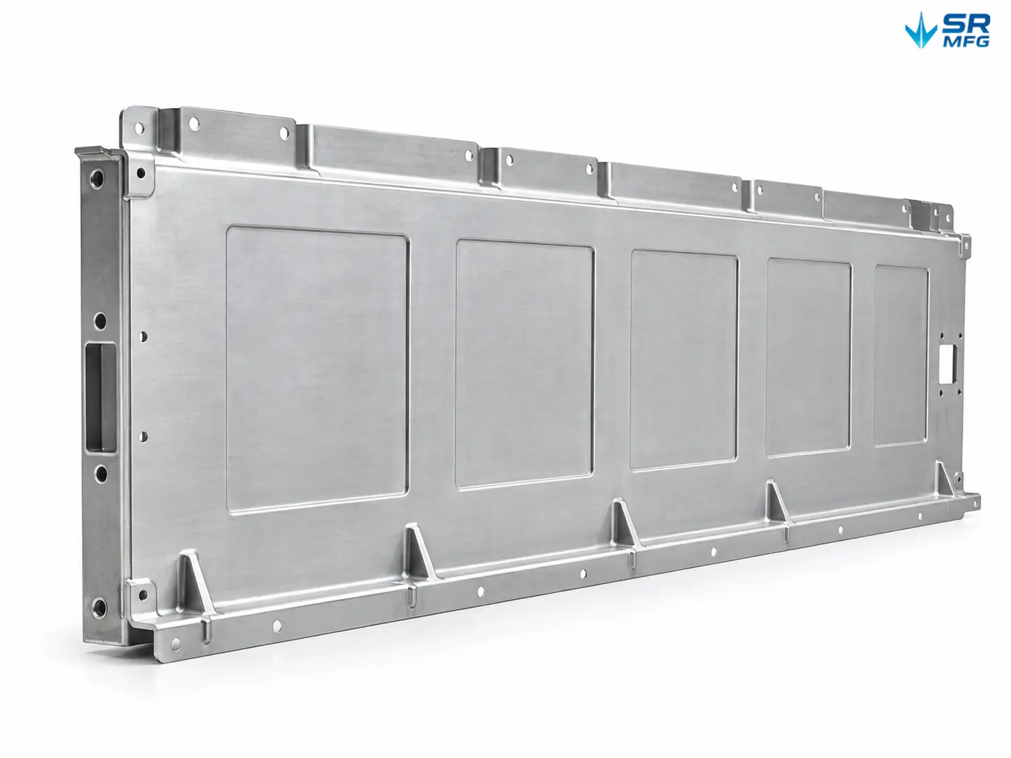
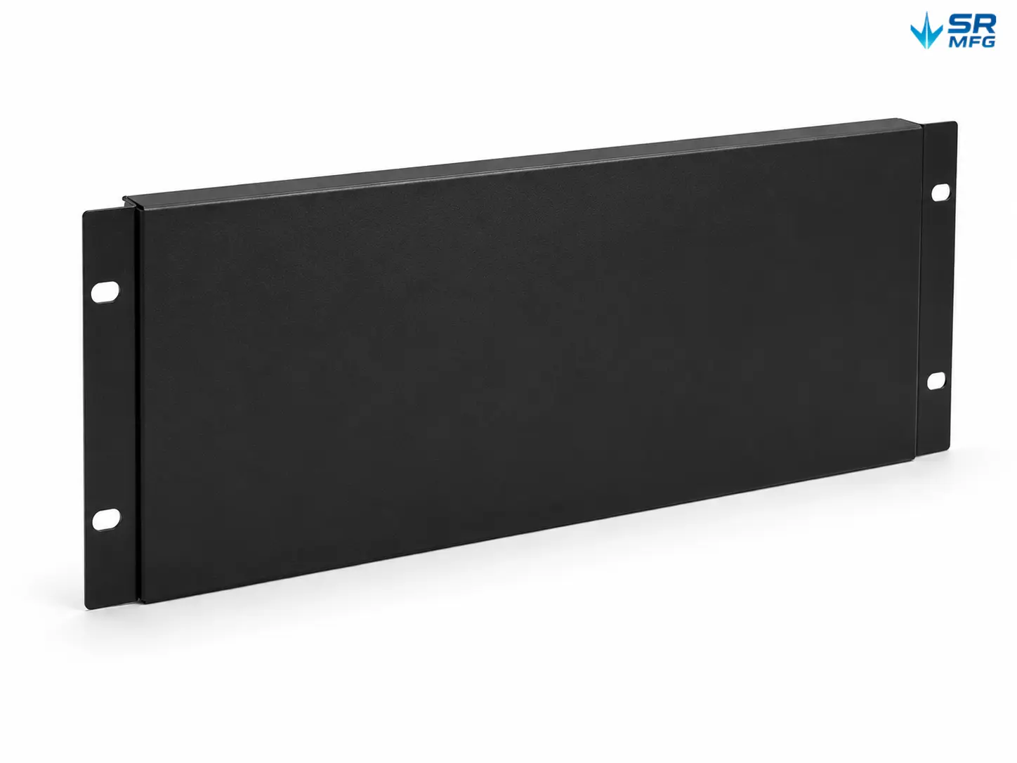
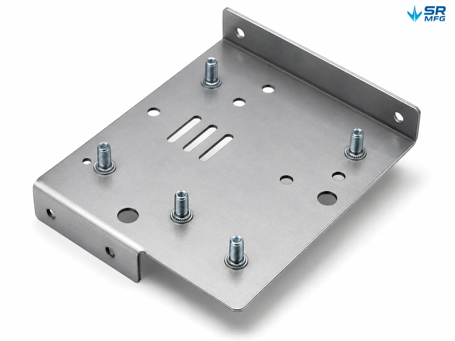
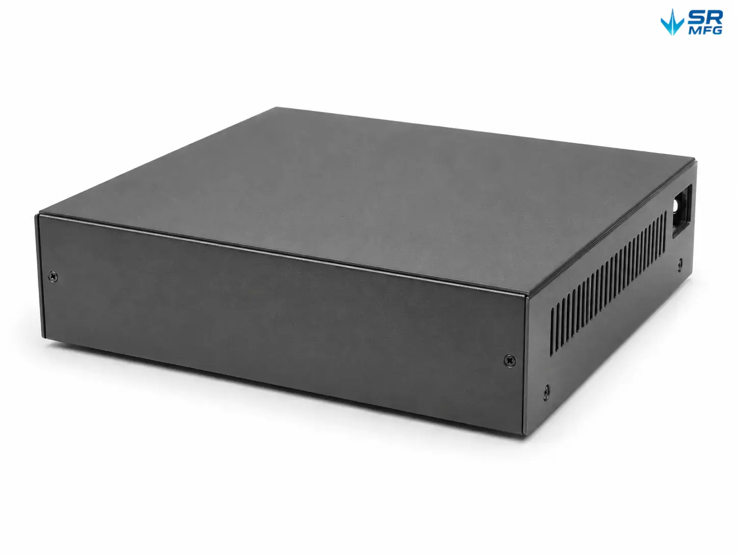
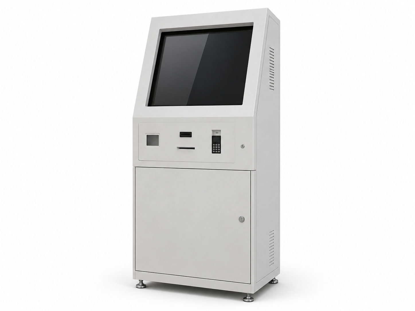
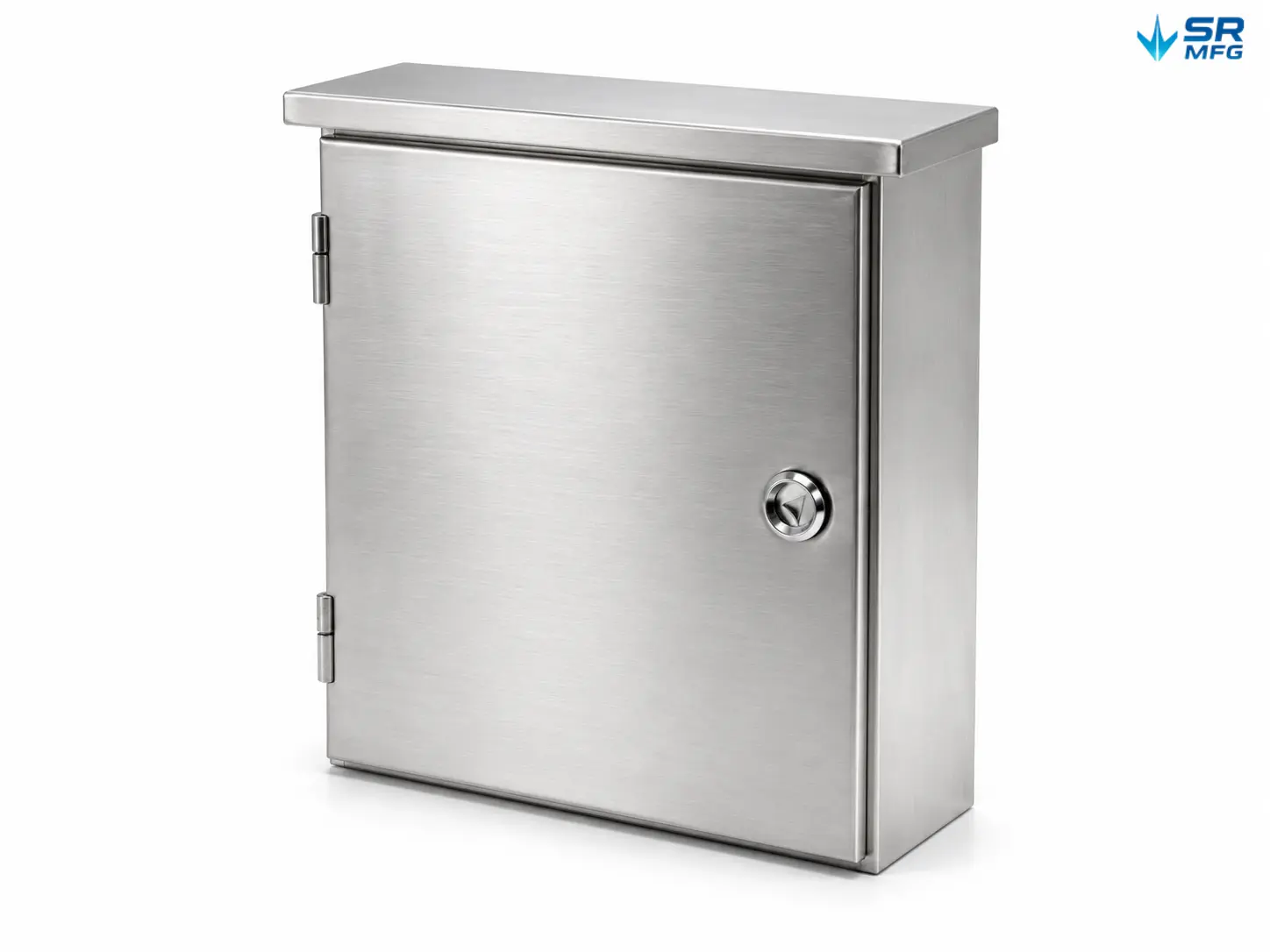
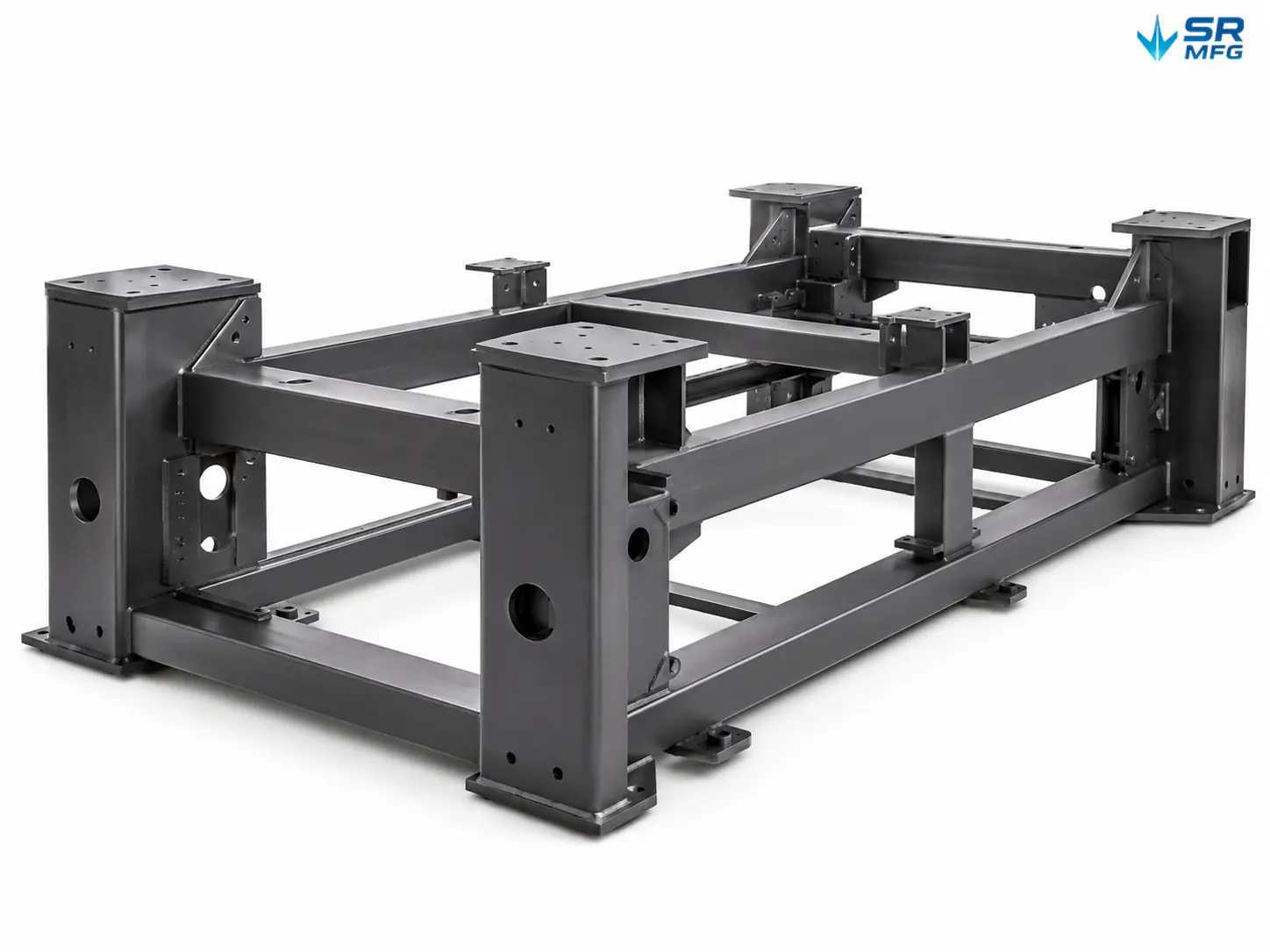
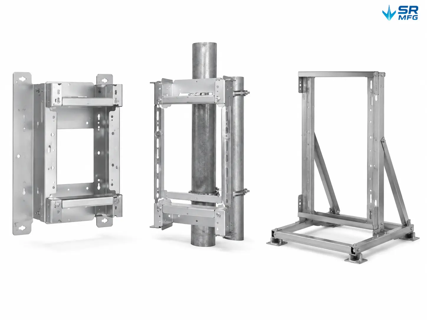
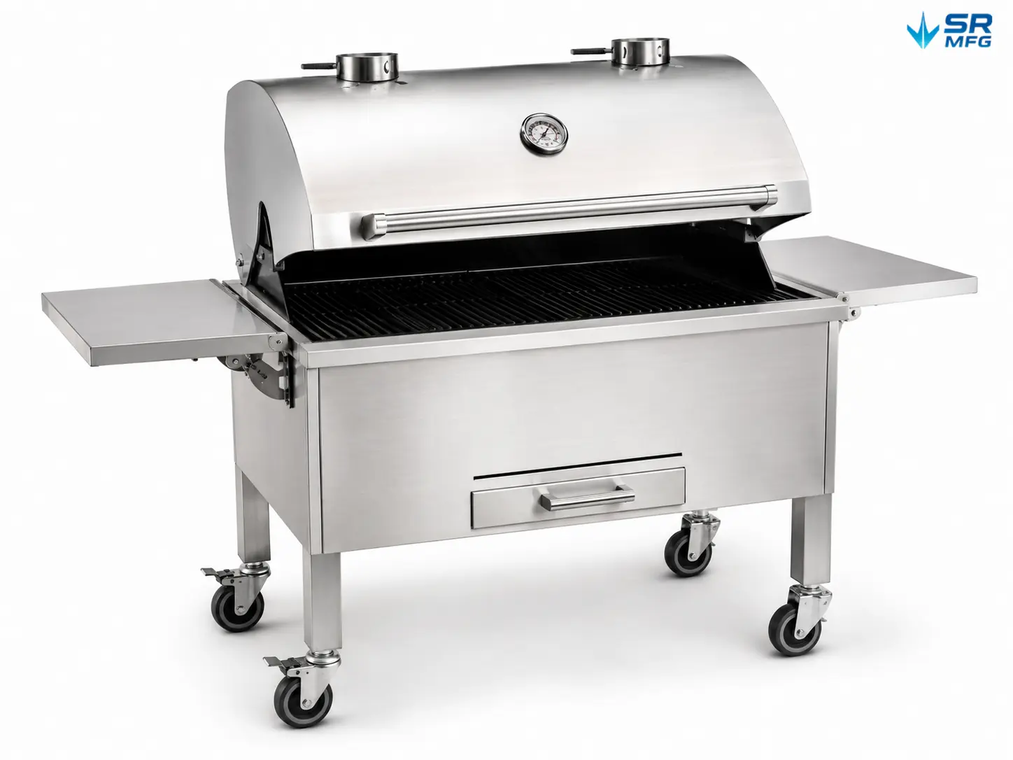
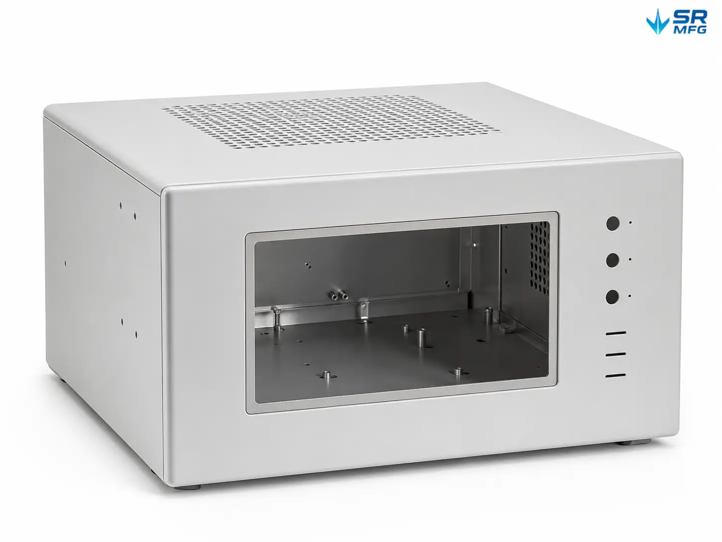
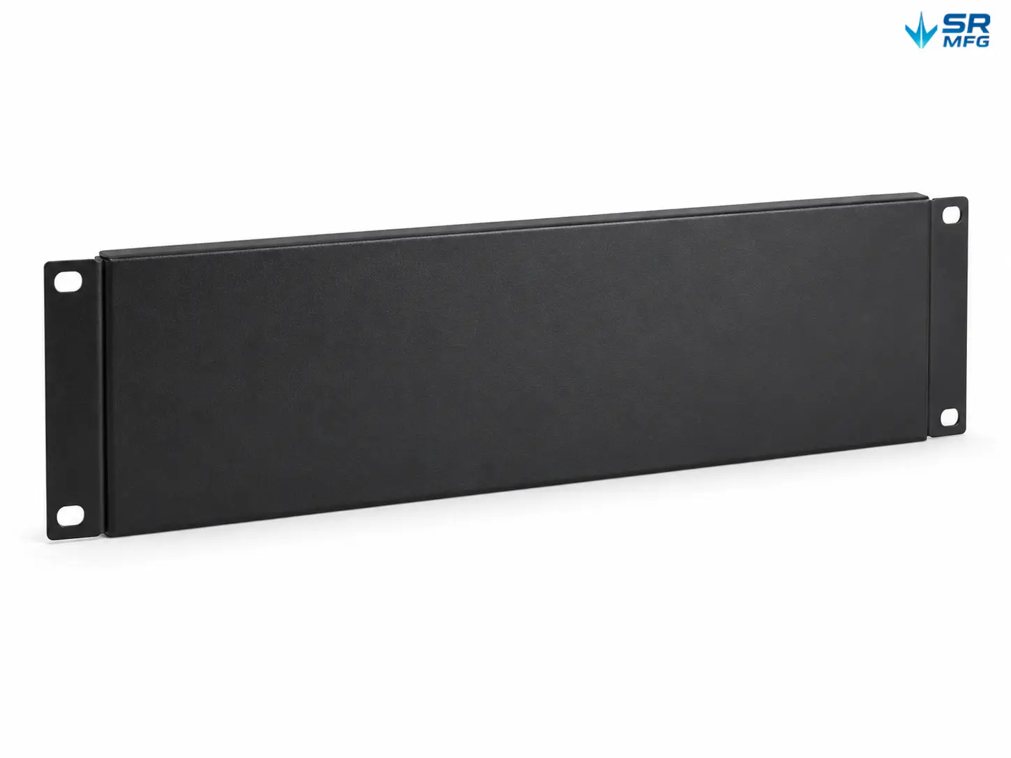
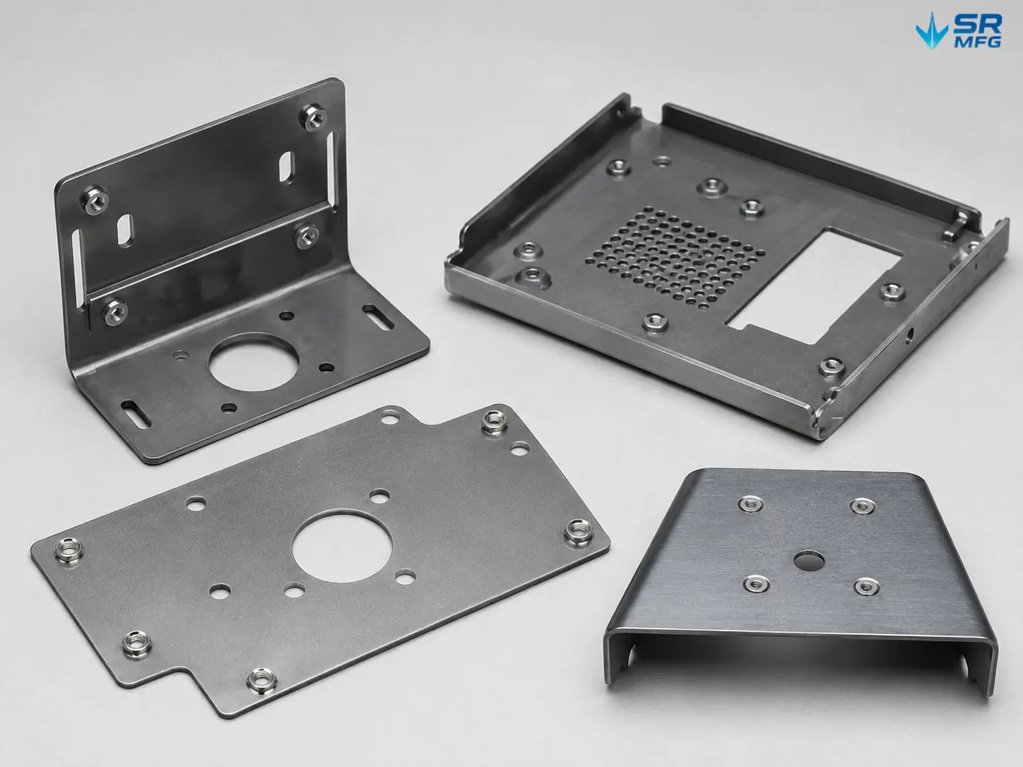
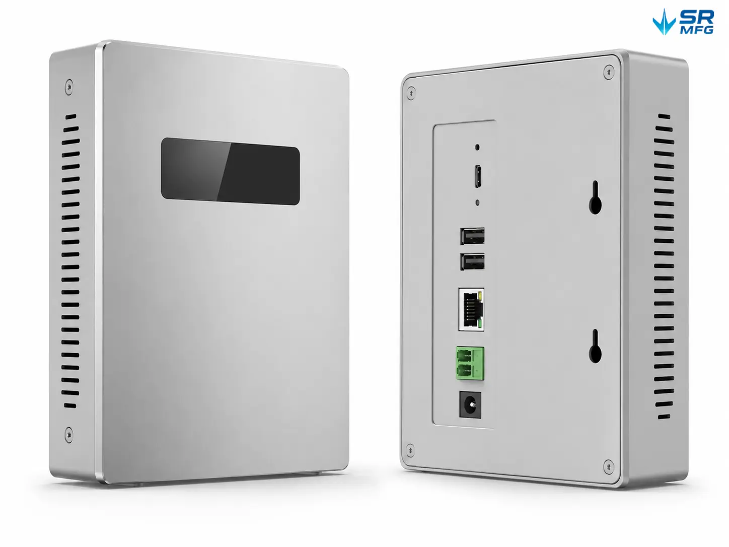
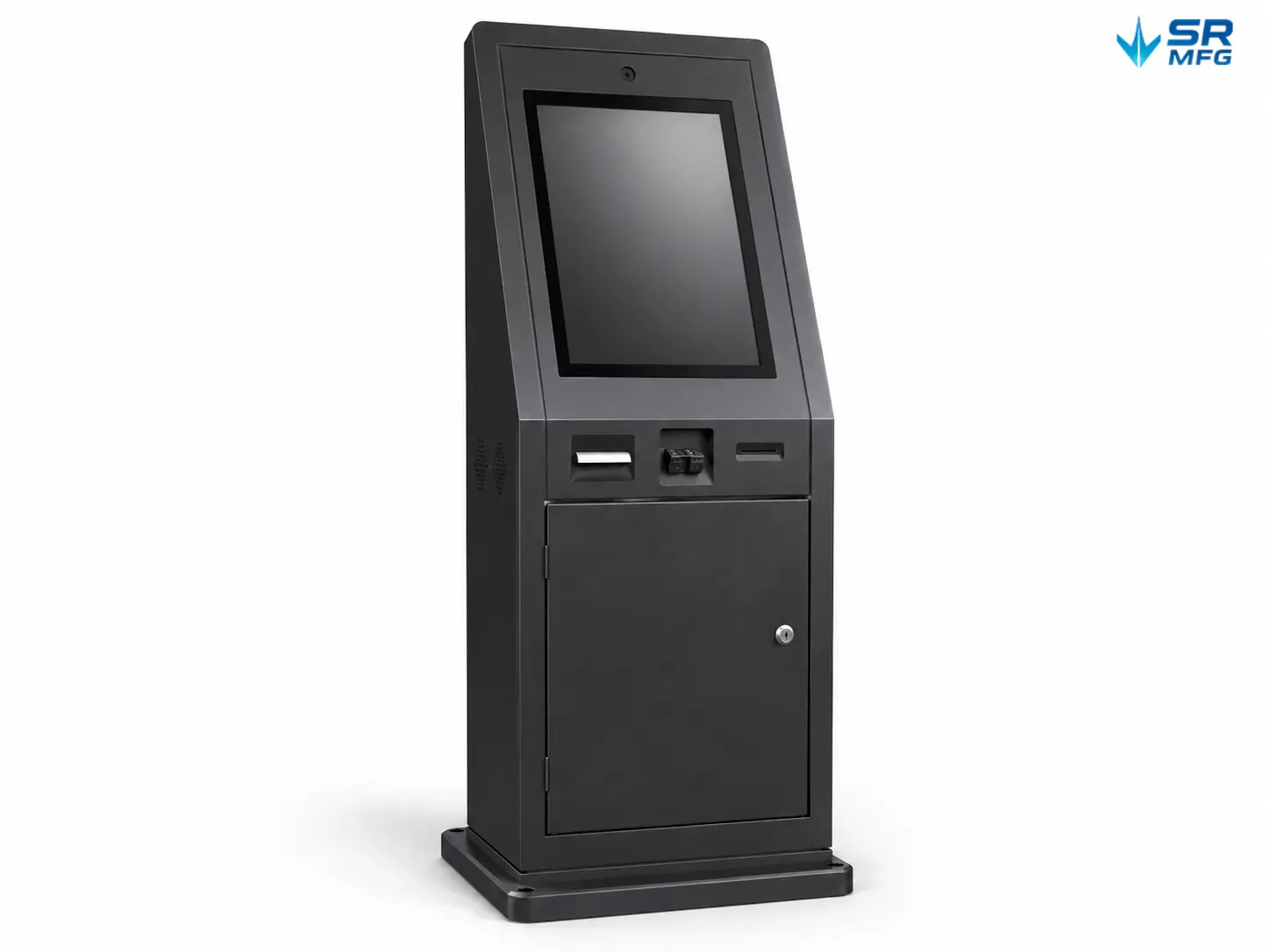
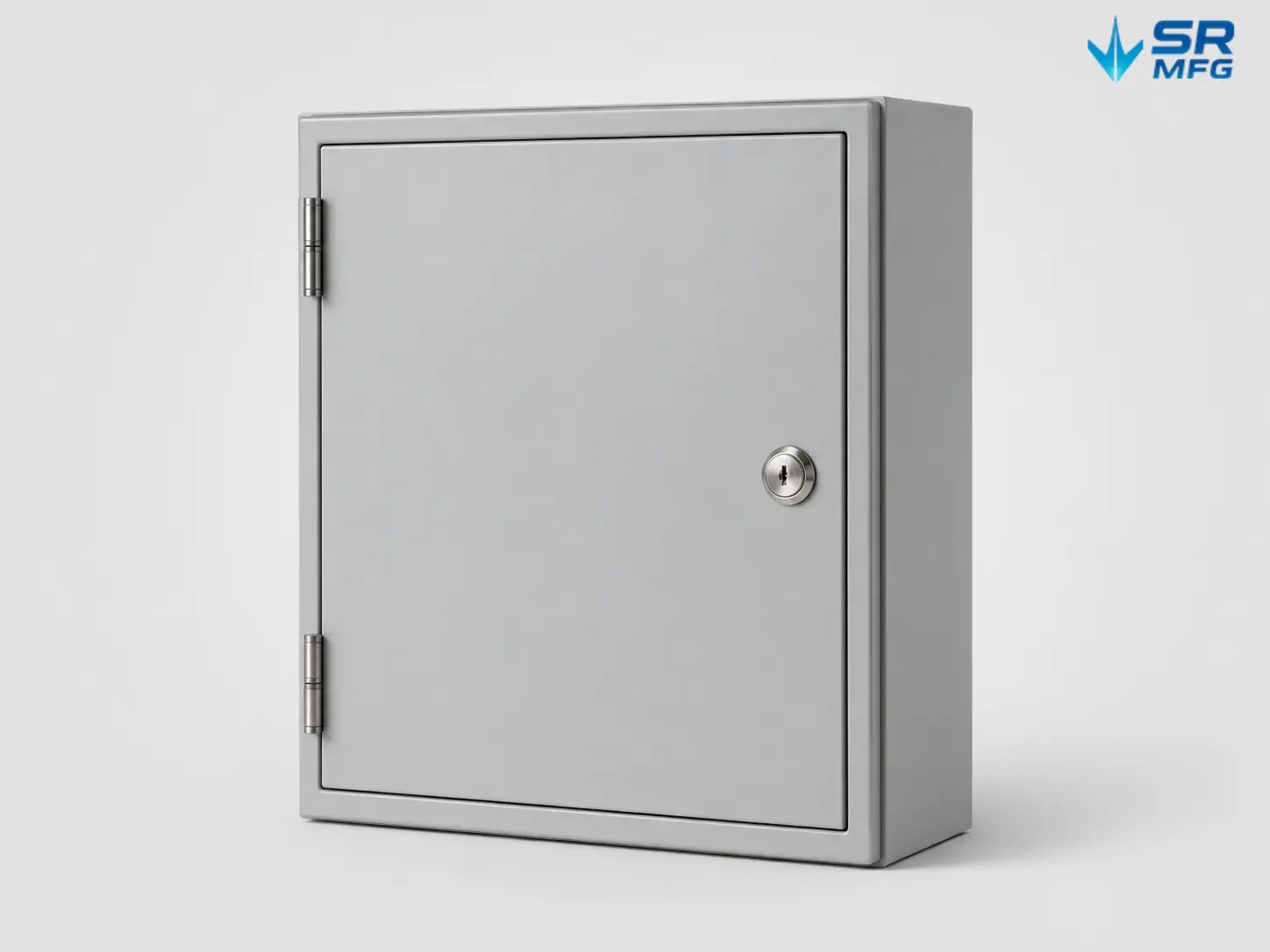
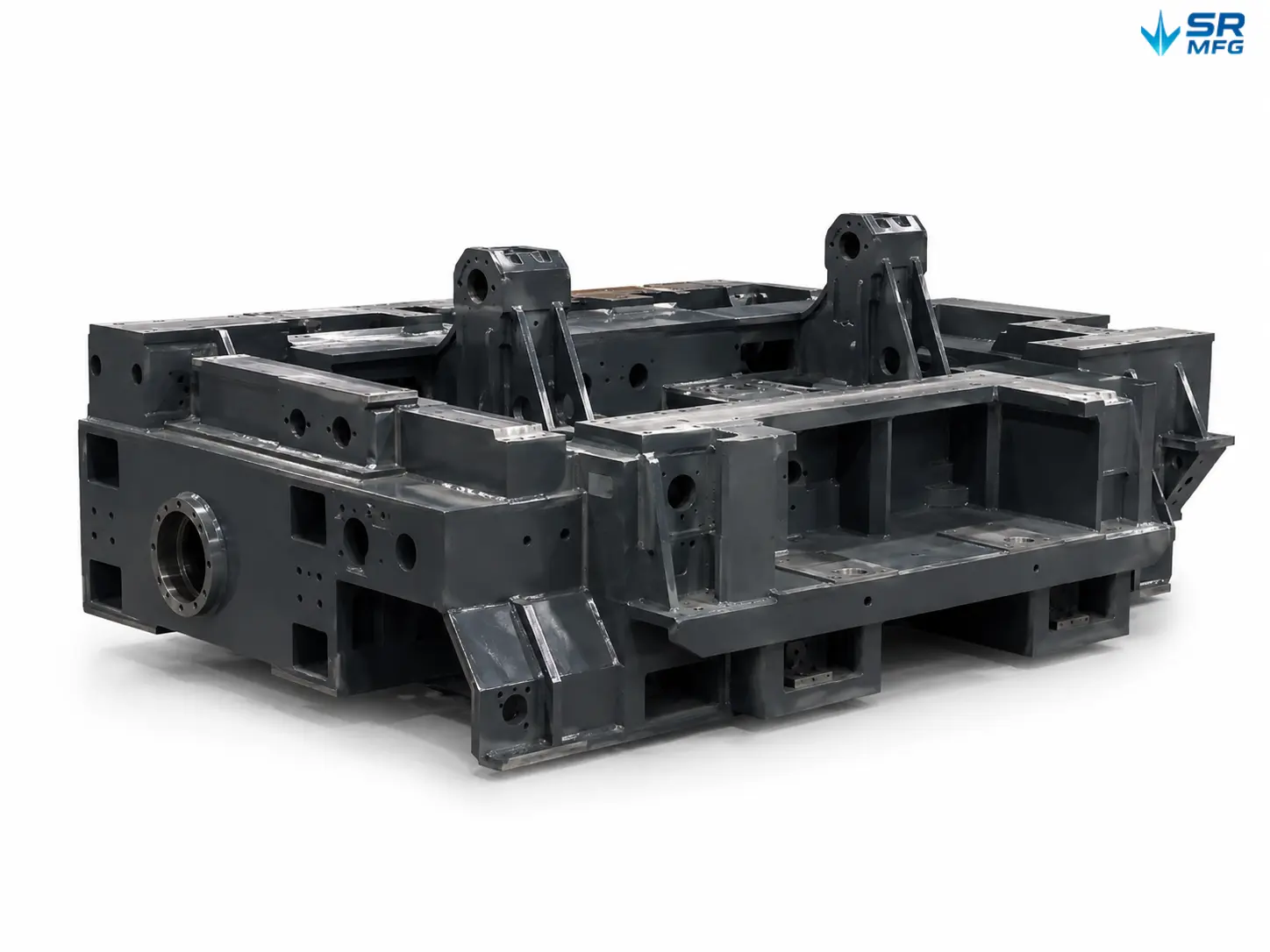
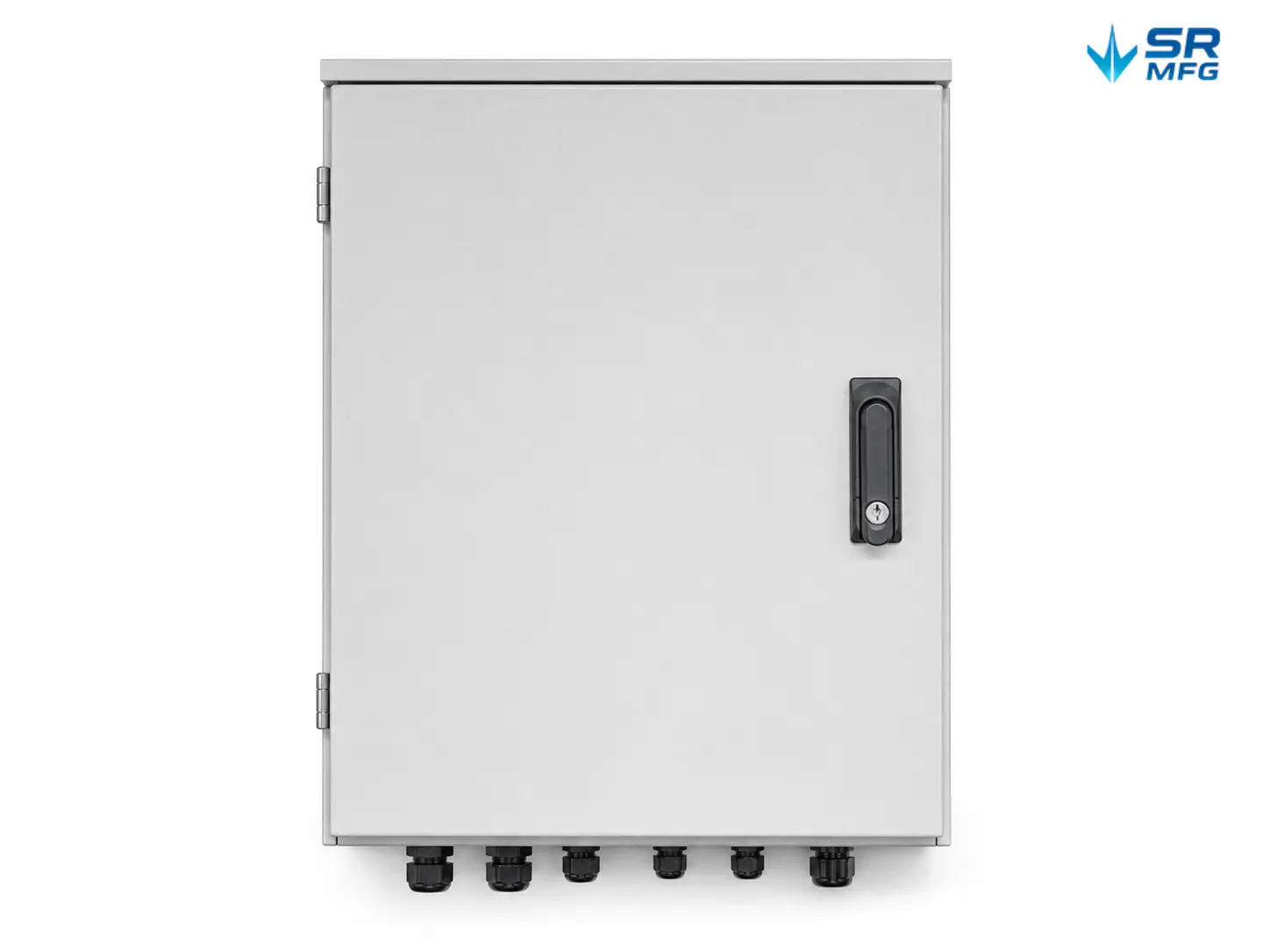
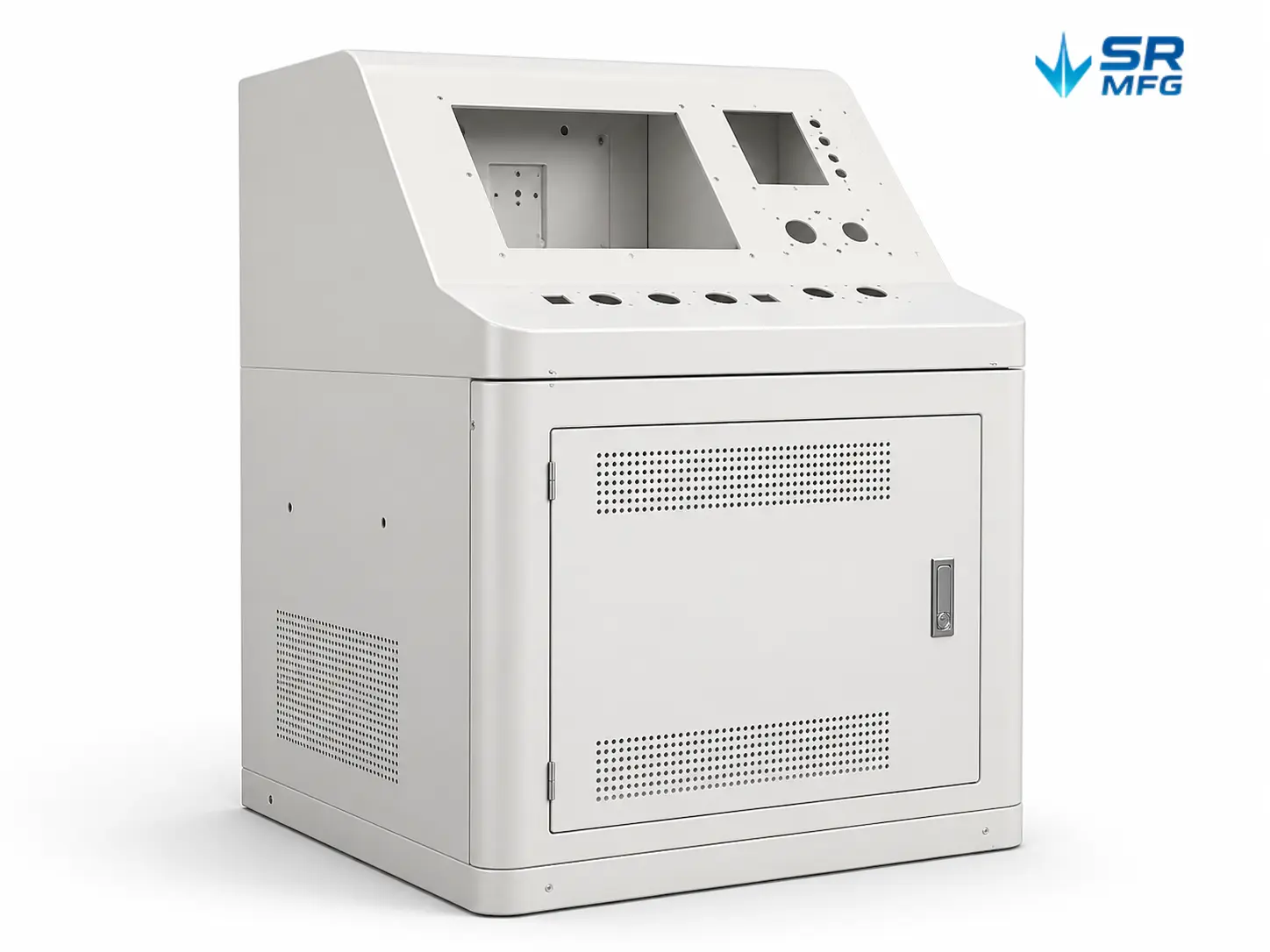
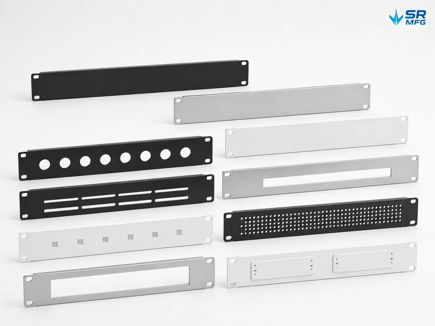
Laser-cut products designed and manufactured by SR MFG

SR MFG has collaborated with global OEMs to co-design and manufacture a variety of custom sheet metal products, covering enclosures, chassis, panels, brackets, and structural components.

よくある質問 about laser cutting

Our sheet-metal laser cutting process typically maintains ±0.1 mm dimensional accuracy on carbon steel, stainless steel and aluminum parts.

Critical features—such as mounting holes, alignment slots and bending-related edges—are controlled within a tighter internal tolerance window based on material thickness and part geometry.
Batch consistency is supported by a controlled process window, FAI + in-process inspection + SPC, ensuring repeatability for long-term OEM production.

  • Prototype laser-cut parts: usually 3–7 working days, depending on part complexity and downstream operations (bending or welding).
  • Mass production orders: standard batch runs ship within 10–20 working days; multi-stage OEM assemblies typically follow a 3–4 week cycle.
    Our workflow is built around predictable lead times, rapid DFM feedback and stable scheduling—important for automation equipment, industrial cabinets and EV component manufacturers.
Laser cutting supports most metals used in OEM fabrication, including steel, stainless steel, aluminum and coated steel.

However, several materials require caution or alternative methods:

  • Highly reflective metals (e.g., copper, pure brass, mirror-finish aluminum) may require special parameters.

  • Composite or sandwich panels have inconsistent heat reactions and may not deliver clean edges.

  • PVC or chlorine-containing materials are unsuitable due to hazardous fumes.
    If material behavior is uncertain, we provide parameter testing before prototype approval.


To ensure accurate and fast processing:
  • DXF / DWG files should have closed profiles, no overlapping lines, and use millimeters as the base unit.

  • STEP (3D) files are recommended when bending, welding or enclosure assembly is required—this allows a complete DFM review and unfolding verification.

  • For bent sheet-metal parts, please provide the formed 3D model and a 2D drawing with critical dimensions, bend directions, and tolerances. SR MFG can develop the flat pattern based on the selected material and bending process.

Yes. Our laser cutting services integrate downstream finishing to support OEM-level consistency:
  • Mechanical deburring

  • Edge rounding

  • Surface brushing / polishing

  • Powder coating, electrophoresis, galvanizing and other protective coatings
    This prevents variation caused by external subcontracting and ensures that laser-cut components enter bending, welding or assembly without additional preparation.

Yes. Our factory is structured for stable, repeatable OEM production:
  • Material batch traceability + MTC + CoC

  • ISO 9001 production control

  • Process parameter library for consistent cutting quality

  • Scalable capacity from 1 pc to high-volume production

  • Repeatability ensured by controlled workflows (FAI, inspection, SPC)
    We support annual demand forecasting, customized packaging for global shipping, and long-term supply programs for automation machinery, electrical cabinets, industrial laser cutting parts, and industrial enclosures.

Laser cutting technology resources

トップへ戻る