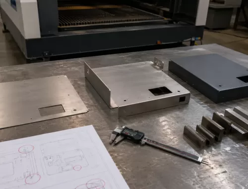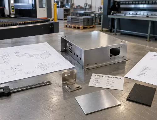

A 板金図面における単一の公差指示が、見積価格に20〜40%を上乗せすることがあります — 適切に最適化されれば、同じ金額を節約できます。. OEMエンジニアおよび調達チームにとって、問題は公差最適化が機能するかどうかではありません。. 問題は、その投資がお客様の特定の部品、生産量、および現在のプロジェクト段階にとって意味があるかどうかです。.
本記事では、板金加工における公差最適化が実際に何を伴うか、そのコスト、節約できる内容、そして最も重要なこととして、次の発注で追求する価値があるかどうかを判断する方法を解説します。.
板金部品における公差最適化の実際の意味
公差最適化とは、図面上のすべての寸法を見直し、機能的に必要な公差を特定し、不要なものを緩和するプロセスです。. 仕様を一律に緩めることではありません。. それは的を絞った再配分です:機能が要求する箇所では厳しく、それ以外はすべて標準に。.
この用語は、関連するが異なる2つの活動と混同されることがよくあります。 DFMレビュー (設計製造性)は、曲げ半径、穴配置、材料選択、溶接アクセスなど部品全体を検討し、製造が困難または高コストな特徴を指摘します。公差最適化はより狭義です:図面上の寸法および幾何公差指示が部品の機能によって正当化されるかどうかに特化して焦点を当てます。 公差スタックアップ解析 は、複数の部品間のばらつきがアセンブリ内でどのように組み合わされるかを計算します。公差最適化はスタックアップ結果を使用することがありますが、その範囲は重要なアセンブリチェーン内のものだけでなく、図面上のすべての寸法に及びます。.
板金公差が機械加工品や成形品と異なる挙動をする理由
CNC機械加工では、切削工具はプログラムされた経路に従い、比較的一貫して±0.005″(0.13 mm)またはそれより厳しい公差を維持できます。射出成形では、金型は固定されており、ショットごとにほぼ同一の部品を生産します。. 板金加工は異なります。.
レーザー切断は維持できます ±0.005″(0.13 mm) プロファイル寸法において。しかし、曲げ公差は本質的に精度が低くなります — 通常 角度で±0.5° および フランジ長で±0.010″(0.25 mm) 標準的なプレスブレーキ作業の場合。各曲げはスプリングバックを生じ、スプリングバックは材料、圧延方向、工具摩耗、および周囲温度によって変動します。部品に複数の曲げがある場合、それらの曲げにわたる累積誤差は達することがあります ±0.020–0.030″(0.5–0.75 mm) 個々の寸法が仕様外になることなく。.
これは、3つの曲げに依存する特徴に±0.005″の公差を指定することが、高コストであるだけでなく — 機械加工や反復的な手合わせなどの二次工程なしには物理的に達成不可能である可能性があることを意味します。. この製造上の現実を理解することが、意味のある公差の議論の出発点です。.
板金見積もりにおいて過剰公差がコストを隠す場所
加工業者がすべての寸法に厳しい公差が付いた図面を受け取ると、見積もりはリスクを反映します。. 加工業者は、どの公差が重要で、どれが以前の設計からコピーされたか、または「念のため」に厳しくされたかを知りません。“ そのため、彼らは最悪のケースで価格設定します。. ここでそのコストが実際にどこに発生するかを示します。.
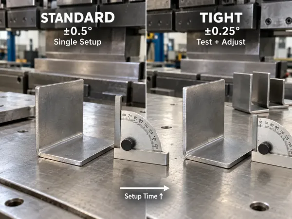
過剰公差は、段取り、検査、スクラップ、および二次加工コストを増加させる可能性があります。.
レーザー切断:厳しい公差は送り速度を低下させ、薄板ゲージでのスクラップを増加させる
板金の標準的なレーザー切断公差は±0.005″(0.13 mm)です。図面が切断特徴に±0.002″(0.05 mm)を要求する場合、オペレーターは送り速度を下げ、より細かいガス圧設定を使用し、より頻繁なキャリブレーションチェックを実行する必要があります。薄いゲージ(1 mm未満)では、厳しい公差は熱変形のリスクも増加させます — 熱影響部が特徴サイズのより大きな割合を占め、スクラップ率が上昇します。.
コストへの影響は単一の特徴では劇的ではありませんが、複合します。. 30個の穴すべてが±0.005″ではなく±0.002″で指定された部品は、切断に時間がかかり、検査中により多くの部品が拒否されます。4つの取り付け穴のみが厳しい仕様を持つ部品と比較して。.
曲げ:角度およびフランジ長公差がプレスブレーキの段取り時間を左右する
曲げは、板金において公差コストが最も顕著にエスカレートする場所です。±0.5°の角度公差は、標準工具と単一の段取りで達成可能です。それを±0.25°に厳しくすると、オペレーターはテスト曲げを実行し、分度器またはCMMで測定し、ラム深度を調整し、繰り返す必要があります — 最初の良品ができるまでにしばしば2〜3回の反復。. 50個の少量生産では、その段取り時間は総曲げコストの30〜50%を占めることがあります。.
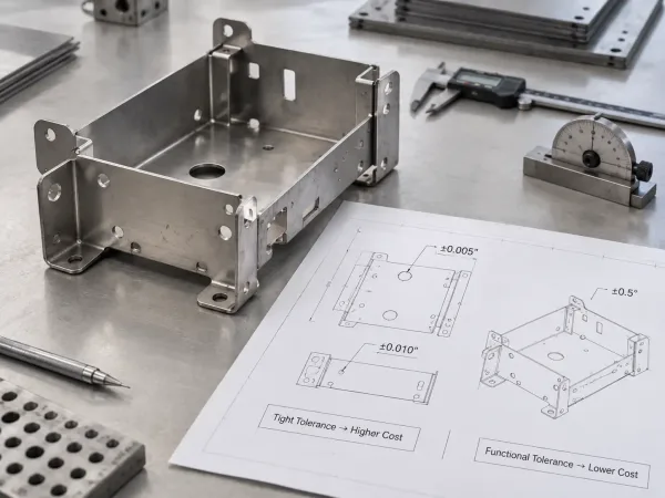
厳しい曲げ公差は、しばしばテスト曲げ、追加測定、および繰り返しの段取り調整を必要とします。.
フランジ長公差も同じパターンに従います。. ±0.010″ は標準です;; ±0.005″ は慎重なバックゲージ位置決めが必要で、フランジが短いか材料が厚い場合は専用治具が必要になることがあります。. 単一の曲げにおけるこれら2つの公差レベルのコスト差は 0.50–部品あたり2.00 — 数百の部品と複数の曲げにわたって乗算されると、すぐに積み上がります。.
溶接とアセンブリ:成形後の歪みが一部の厳しい公差を物理的に達成不可能にする
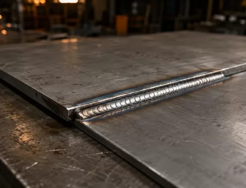
溶接を必要とする板金部品は、追加の課題に直面します:熱歪み。. 5 mmステンレス鋼へのTIG溶接は、0.5~1.0 mmの局所的な歪みを生じさせる可能性があります。. 図面が溶接部を横切る寸法に±0.010″の公差を指定している場合、溶接後の機械加工または溶接中に部品を拘束状態に保持する治具なしでは、その部品の製造は不可能かもしれません——そのどちらも大幅なコスト増となります。.
これは、設計意図と製造現実の間の最も一般的な衝突原因の一つです。エンジニアはCADモデルの公称形状に基づいて厳しい公差を指定します。製作側は、溶接によって材料がその公差を超えて動くことを知っています。. その結果は、高い見積もり(治具と手直しのコストを反映)か、プロジェクトを遅延させる clarification の要求のどちらかです。.
検査:追加の重要寸法ごとにCMM時間と治具コストが増加する
図面上で重要としてマークされた各寸法は、検証されなければなりません。. 板金部品の場合、検証は通常、CMM(三次元測定機)検査または光学比較を意味します。重要寸法が5つの部品では、検査に10~15分かかる場合があります。重要寸法が20の部品——そのうち15が非機能的な「保険」公差——では、45~60分かかる可能性があります。.
典型的なCMM検査料率**75–**150/時間, では、その余分な30~45分は 37–検査コストだけで部品あたり112ドル追加されます。. 200個のバッチでは、 7,400–形状、適合、機能に影響しない寸法の検証に22,400ドルが費やされます。.
公差最適化コンサルティングの実際のコスト
公差最適化のコストは、誰が行うか、関与する部品数、および契約の構成によって異なります。.
時間単価の範囲
オフショアのGD&Tおよび公差分析スペシャリスト(通常、インド、東欧、または東南アジア)は**15–**35/時間. を請求します。米国、カナダ、または西ヨーロッパの国内コンサルタントは**150–**350/時間, を請求し、料率は分析の複雑さと業界(航空宇宙および医療が最高料率)を反映しています。.
ほとんどのOEM板金プロジェクトでは、オフショア料率範囲は単純な公差レビューに関連し、国内コンサルタントは安全上重要なインターフェースを持つ複雑なアセンブリにより適しています。.
プロジェクトベースの価格設定
典型的な公差監査は 10~50の板金部品 ——寸法分類、重要嵌合部のスタックアップ分析、緩和の推奨を含む——は**3,000–**15,000 複雑さとコンサルタントの所在地に応じて**かかります。100以上の部品またはマルチアセンブリシステムを含む大規模な監査は**25,000–**50,000.
に達する可能性があります。重要な指標は部品あたりのコストです。. 30部品の監査で$5,000の場合、部品あたり約$167を支払うことになり、これは生産で部品あたり 0.50–00ドルを節約できるレビューです——ほとんどの中量生産注文で最初の生産実行内に回収できるリターンです。.
隠れたコスト:サプライヤーが公差問題を修正する際に請求するもの
製作側が過剰公差の寸法を含む図面を受け取った場合、単純に公差を緩和して再見積もりするわけではありません。. 彼らは問題にフラグを立て、 clarification を要求し、回答を待ち、再見積もりします——通常 3~7営業日 を見積もりプロセスに追加するサイクルです。製作側が問題にフラグを立てずに図面通りに見積もる場合、見積もりには手直し、より高いスクラップ、または長い段取り時間の予想を反映するリスクプレミアムが含まれます。.
実際には、多くの製作側はDFMレビュー中に公差緩和を提案することで、このコストの一部を吸収します。しかし、そのDFMフィードバックは、製作側が直接請求しないという意味で無料なだけです。コストは関係性に埋め込まれています:過剰公差の図面を繰り返し受け取るサプライヤーは、最終的に図面がよりクリーンな顧客を優先するようになります。.
意思決定フレームワーク——公差最適化はいつ投資に値するか?
すべてのプロジェクトが公差最適化から等しく恩恵を受けるわけではありません。ROIは4つの要因に依存します。.
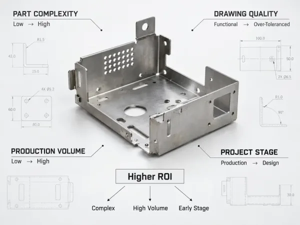
公差最適化は、プロジェクト初期の複雑で高量の部品で最も強いROIを提供します。.
要因1——部品の複雑さ:図面にはいくつの重要嵌合と嵌合インターフェースがあるか?
A simple bracket with 3 holes and 1 bend has very few dimensions that could be over-toleranced. The cost savings from optimization are small, and the consulting investment may not pay back. An enclosure with 40+ features, multiple bends, welded seams, and 10 mounting interfaces that mate with another assembly has far more room for tolerance to drive cost — and far more room for optimization to save money.
経験則:部品に機能にとって重要である可能性が高い寸法が10未満の場合、公差最適化が意味のある節約を提供する可能性は低いです。20以上ある場合、通常は計算が合います。.
要因2——現在の図面品質:公差は機能ベースか「保険公差」か?
一部の図面には、アセンブリ要件、スタックアップ分析、および機能テストから慎重に導出された公差が含まれています。他のものには、類似部品からコピーされた、CADソフトウェアが提供する最も厳しいレベルで指定された、または現在の設計とは無関係の過去の品質インシデント後に厳しくされた公差が含まれています。.
あなたの図面が2番目のカテゴリに該当する場合——そして業界経験は、典型的なエンジニアリング図面の公差の 60~80%が機能要件が要求するよりも厳しいことを示唆しています ——節約の可能性は significant です。公差監査は、どのコールアウトが正当化され、どのコールアウトが価値を提供せずにコストをかけているかを特定できます。.
要因3——生産量:低量対高量が部品あたりのコスト計算を変える
10部品のプロトタイプランの場合、公差最適化による絶対的な節約は小さいです。. Relaxing a tolerance might save $2 per part — $20 total. The consulting cost will not pay back.
For a production run of 5,000 parts, the same $2 per part savings becomes $10,000. For a product with an annual volume of 20,000 parts and a 5-year lifecycle, it becomes $200,000. The consulting investment of $5,000–$15,000 looks different at each volume level.
The crossover point: Most tolerance optimization investments pay back within the first production run when annual volume exceeds 500–1,000 parts. Below that, the ROI is marginal unless the parts are highly complex or the current tolerances are dramatically over-specified.
Factor 4 — Project Stage: Design, Quoting, Prototype, or Production — Where You Are Determines the ROI
Tolerance optimization delivers the highest ROI when done before the first quote is sent. At the design stage, changing a tolerance on a drawing takes minutes and costs nothing. At the quoting stage, it can prevent a risk premium from being added to the quote. At the prototype stage, it can eliminate the need for rework or secondary operations. At the production stage, it can still reduce inspection cost and scrap, but the tooling and process decisions are already locked in, and the savings are smaller.
The 10× rule applies here: a tolerance issue that costs $1 to fix in design costs $10 to fix in quoting, $100 to fix in prototype, and $1,000+ to fix in production.
What a Sheet Metal Tolerance Audit Delivers
A structured tolerance audit follows a defined sequence. Here is what the process looks like when applied to sheet metal parts.
Step 1 — Classify Every Dimension: Critical-to-Function vs. Non-Critical
The auditor reviews every dimension on the drawing and classifies it as CTF (critical-to-function) — meaning it directly affects fit, sealing, alignment, or structural performance — or non-critical, meaning it can be relaxed to standard process tolerances without affecting how the part works.
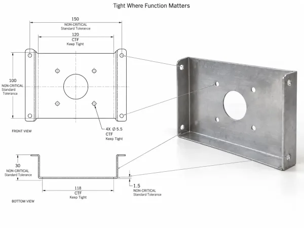
Tolerance optimization keeps critical functional dimensions tight while relaxing non-critical dimensions.
In practice, CTF dimensions typically represent 5–15% of all dimensions on a sheet metal drawing. The rest are clearance holes, trim edges, non-mating surfaces, and features whose tolerances were inherited rather than derived.
Step 2 — Run Tolerance Stack-Ups on Mating Interfaces
For every CTF dimension that participates in an assembly, the auditor runs a tolerance stack-up analysis — either worst-case (for safety-critical interfaces) or statistical (RSS or Monte Carlo, for most commercial applications). This determines whether the specified tolerance is necessary, sufficient, or unnecessarily tight given the tolerance budget of the assembly.
A common finding: a mounting hole pattern specified at ±0.005″ when the mating part has ±0.010″ clearance holes. The stack-up shows that ±0.010″ on the mounting holes would still achieve the required fit — and cost significantly less to produce.
Step 3 — Match Tolerances to Process Capability
The auditor maps each CTF tolerance against the process capability of the intended manufacturing method. For sheet metal, the reference points are:
| Process | Typical Capability | Tighter Requires |
|---|---|---|
| Laser cutting (profile) | ±0.005″(0.13 mm) | Reduced feed rate, more scrap |
| Punching | ±0.003″ (0.08 mm) | Tooling condition, punch-die clearance |
| Bending (angle) | ±0.5° | Iterative setup, test bends |
| Bending (flange length) | ±0.010″ (0.25 mm) | Dedicated fixture, CMM verification |
| Welding (post-form position) | ±0.020–0.030″(0.5–0.75 mm) | Welding fixture, post-weld machining |
| PEM hardware installation | ±0.010″ (0.25 mm) | Manual alignment, fixture |
Tolerances that fall within the process’s natural capability are straightforward to produce. Tolerances that require capability beyond the standard range carry a cost premium that should be justified by function.
Step 4 — Deliver the Optimized Drawing
The final deliverable is a revised drawing (or a marked-up review package) with:
- CTF dimensions retained with their original (or refined) tolerances
- Non-critical dimensions relaxed to ISO 2768-m (medium) general tolerances or process-standard ranges
- GD&T callouts added or corrected where they improve communication of functional intent
- A summary of changes with cost impact estimates
The goal is a drawing that communicates exactly what matters and nothing more — giving the fabricator the flexibility to produce the part efficiently while protecting every dimension that affects performance.
How to Push Tolerance Optimization Through Your Supplier Relationship
Even when the engineering team understands the value of tolerance optimization, implementation often stalls at the supplier interface. Here is how to make it work in practice.
What to Include in Your RFQ to Get Tolerance Feedback Early
Most fabricators will flag obvious tolerance issues during quoting — but only if the RFQ gives them enough context to do so. Include the following with your drawing package:
- Assembly context: a note or separate drawing showing how this part mates with adjacent components
- Critical dimensions list: explicitly mark which 3–5 dimensions are CTF and why
- Quantity and annual volume: fabricators price tolerance risk differently for 50 parts vs. 5,000
- Finish and material: these affect achievable tolerances and should be confirmed before quoting
A drawing with 40 tight dimensions and no indication of which ones matter forces the fabricator to either quote high (assuming all are critical) or spend time asking questions that delay the quote by days.
How to Read a Supplier’s DFM Comments on Tolerances
When a fabricator suggests relaxing a tolerance, they are not trying to cut corners. They are telling you that the specified tolerance adds cost — and that, based on their experience producing similar parts, a wider tolerance would be functionally equivalent.
The right response is not “hold to print” by default. It is to ask: “What is the functional risk if this tolerance is relaxed to [their suggestion]?” If the fabricator can explain why the relaxed tolerance still meets the assembly requirement, accept it. If they cannot, hold the tolerance — but understand that you are paying for precision that may not be necessary.
When to Accept the Supplier’s Suggestion and When to Push Back
Accept the suggestion when:
- The fabricator points to a specific dimensional relationship (e.g., “this hole mates with a clearance slot on the other part — ±0.010″ is sufficient”)
- The tolerance was inherited from a previous design without specific functional justification
- The stack-up analysis supports the relaxed value
Push back when:
- The dimension controls a sealing interface, a press-fit, or a safety-critical alignment
- The fabricator’s suggestion is based on their process limitations rather than your functional requirements (in which case, the solution may be a different manufacturing method, not a relaxed tolerance)
- You have test data or field failure history that validates the original tolerance
The goal is a collaborative conversation, not a negotiation. The best outcomes happen when the OEM shares functional context and the fabricator shares process context — and both sides use that information to find the tolerance that is tight enough and not tighter.
よくある質問